


Chapter 2
Design and Function
5300.9677.72
- 2.3 -
EN-4
CONTENTS
1 Design and Function ....................................................................... 4
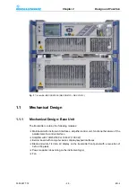
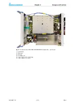
1.1.1 Mechanical Design: Base Unit .....................................................................5
1.1.2 Mechanical Design: Separate Amplifier .....................................................11
1.2.1 Rear Panel Connections: Base Unit ...........................................................12
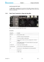
1.2.2 Rear Panel Connections: Separate Amplifier .............................................15
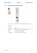
1.2.3 Front Panel Connections: Base Unit ..........................................................16
1.2.4 Front Panel Connections: Separate Amplifier ............................................17
1.3.1 Input Screen ...............................................................................................17
1.3.2 Function Keys and Displays: Base Unit .....................................................18
1.3.3 Displays: Separate Amplifier ......................................................................19
2 Specifications ................................................................................ 21
2.1.1 Power Failure .............................................................................................22
2.1.2 Power Supply Fault (R&S SR8010) ...........................................................23
2.1.3 Power Supply Fault (R&S SR8025/SR8050/SR8100) ...............................23
2.1.4 Power Supply Fault (R&S SR8130) ...........................................................24
2.1.5 Power Supply Fault (R&S VU813) .............................................................25
2.1.6 Damage on RF Output Side .......................................................................25
2.1.7 Protection against Overvoltages from the Antenna Cable .........................26
2.1.8 Mechanical Loading ...................................................................................27
Summary of Contents for SR8000 Series
Page 3: ......
Page 7: ...5300 9677 72 0 4 EN 4 ...
Page 8: ...Broadcasting Division 5300 9677 72 1 1 EN 4 Printed in Germany CHAPTER 1 SAFETY ...
Page 9: ......
Page 21: ...5300 9677 72 1 14 EN 4 Chapter1 Safety ...
Page 22: ...Broadcasting Division 5300 9677 72 2 1 EN 4 Printed in Germany CHAPTER 2 DESIGN AND FUNCTION ...
Page 23: ......
Page 27: ...Chapter2 Design and Function 5300 9677 72 2 6 EN 4 Fig 4 R S SR8000 block diagram ...
Page 49: ...Chapter2 Design and Function 5300 9677 72 2 28 EN 4 ...
Page 50: ...Broadcasting Division 5300 9677 72 3 1 EN 4 Printed in Germany CHAPTER 3 INSTALLATION ...
Page 51: ......
Page 63: ......
Page 88: ...Broadcasting Division 5300 9677 71 5 1 EN 4 Printed in Germany CHAPTER 5 OPERATION ...
Page 89: ......
Page 157: ...Chapter5 Operation 5300 9677 71 5 70 EN 4 ...
Page 158: ...Broadcasting Division 5300 9677 72 6 1 EN 4 Printed in Germany CHAPTER 6 MAINTENANCE ...
Page 159: ......
Page 166: ...Broadcasting Division 5300 9677 72 7 1 EN 4 Printed in Germany CHAPTER 7 TROUBLESHOOTING ...
Page 167: ......
Page 168: ...Chapter7 Troubleshooting 5300 9677 72 7 3 EN 4 CONTENTS 1 Information 4 ...
Page 170: ...Broadcasting Division 5300 9677 72 8 1 EN 4 Printed in Germany CHAPTER 8 SERVICE ...
Page 171: ......
Page 184: ...Broadcasting Division 5300 9677 72 9 1 EN 4 Printed in Germany CHAPTER 9 APPENDIX ...
Page 185: ......
Page 197: ...Chapter9 Appendix 5300 9677 72 9 14 EN 4 ...
Page 198: ...Broadcasting Division 5300 9677 72 A 1 EN 4 Printed in Germany WIRING DIAGRAMS ...
Page 199: ......


