


Chapter 2
Design and Function
5300.9677.72
- 2.22 -
EN-4
MPX baseband signal
RF output signal
Forward power/reflected power of standalone instrument
Forward power/reflected power of combined instrument
Miscellaneous amplifier parameters
Fan function
2.1
Protection of Electrical System
The following section describes the faults that can occur in the electrical system of the
transmitter and how the electrical system is protected against these faults.
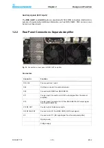
2.1.1
Power Failure
R&S SR8010
: The transmitter has a single phase main power supply for the output stage,
exciter board, and mainboard modules.
R&S SR8025/SR8050/SR8100
: The transmitter has a single phase main power supply for
the output stage module, together with a single phase auxiliary power supply for the exciter
board and mainboard modules.
R&S SR8130
: The transmitter has two single phase main power supplies for the output
stage module, together with a single phase auxiliary power supply for the exciter board and
mainboard modules.
R&S VU813
: The instrument has two single phase main power supplies for the output stage
module, together with a single phase auxiliary power supply for the instrument controller.
In the event of a power failure, a distinction is made between a short interruption of less
than 0.3 s and a long interruption exceeding 0.3 s.
The system is always shut down in the event of long power failures. The exciter is then re-
booted and the transmitter is gradually returned to its pre-shutdown state.
The following scenario applies to short power failures:
– Message on power supply control
Note
The transmitter always returns to the operating mode that it was in prior to the interruption
(automatic restart without manual acknowledgment).
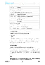
Fault
Protection mechanism
Function
Power failure <0.3 s
No reaction
No reaction
Power failure >0.3
Undervoltage trips power
supply
Shutdown of exciter and amplifier until
power is restored
Summary of Contents for SR8000 Series
Page 3: ......
Page 7: ...5300 9677 72 0 4 EN 4 ...
Page 8: ...Broadcasting Division 5300 9677 72 1 1 EN 4 Printed in Germany CHAPTER 1 SAFETY ...
Page 9: ......
Page 21: ...5300 9677 72 1 14 EN 4 Chapter1 Safety ...
Page 22: ...Broadcasting Division 5300 9677 72 2 1 EN 4 Printed in Germany CHAPTER 2 DESIGN AND FUNCTION ...
Page 23: ......
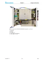
Page 27: ...Chapter2 Design and Function 5300 9677 72 2 6 EN 4 Fig 4 R S SR8000 block diagram ...
Page 49: ...Chapter2 Design and Function 5300 9677 72 2 28 EN 4 ...
Page 50: ...Broadcasting Division 5300 9677 72 3 1 EN 4 Printed in Germany CHAPTER 3 INSTALLATION ...
Page 51: ......
Page 63: ......
Page 88: ...Broadcasting Division 5300 9677 71 5 1 EN 4 Printed in Germany CHAPTER 5 OPERATION ...
Page 89: ......
Page 157: ...Chapter5 Operation 5300 9677 71 5 70 EN 4 ...
Page 158: ...Broadcasting Division 5300 9677 72 6 1 EN 4 Printed in Germany CHAPTER 6 MAINTENANCE ...
Page 159: ......
Page 166: ...Broadcasting Division 5300 9677 72 7 1 EN 4 Printed in Germany CHAPTER 7 TROUBLESHOOTING ...
Page 167: ......
Page 168: ...Chapter7 Troubleshooting 5300 9677 72 7 3 EN 4 CONTENTS 1 Information 4 ...
Page 170: ...Broadcasting Division 5300 9677 72 8 1 EN 4 Printed in Germany CHAPTER 8 SERVICE ...
Page 171: ......
Page 184: ...Broadcasting Division 5300 9677 72 9 1 EN 4 Printed in Germany CHAPTER 9 APPENDIX ...
Page 185: ......
Page 197: ...Chapter9 Appendix 5300 9677 72 9 14 EN 4 ...
Page 198: ...Broadcasting Division 5300 9677 72 A 1 EN 4 Printed in Germany WIRING DIAGRAMS ...
Page 199: ......


