58
Remote Control
special Windows drivers if VISA drivers are installed and
that it can be used directly in corresponding environments.
The GPIB interface serves as model to the structure of the
TMC design. A major benefit of the
USB TMC class is that
by sampling specific registers the user can determine if
commands have been terminated and if they have been
processed correctly. However, the communication via VCP
requires analysis and polling mechanisms within the cont-
rolling software which may significantly strain the interface
of the measurement instruments. The TMC status registers
solve this problem with the USB TMC in the same manner
as is the case with the GPIB interface for the hardware,
namely via corresponding control lines.
14.2.1 USB TMC Configuration
The R&S®HMO1002 resp. R&S®HMO1202 series require a
generic USB instrument driver to be operated in USB-TMC
mode. The USB Test & Measurement class (USB-TMC) is a
protocol that enables GPIB-like communication via USB in-
terfaces and a separate instrument class of the USB speci-
fication. The USB-TMC protocol supports service requests,
trigger and other GPIB-specific commands. The driver is
included in the NI-VISA package (Virtual Instrument Soft-
ware Architecture) and can be downloaded at http://www.
ni.com/downloads/ni-drivers/.
You need to first install the NI-VISA drivers on your Win
-
dows system. Please download the most recent version
of the NI-VISA driver package. Extract the previously
downloaded driver package and follow the installation
instructions.
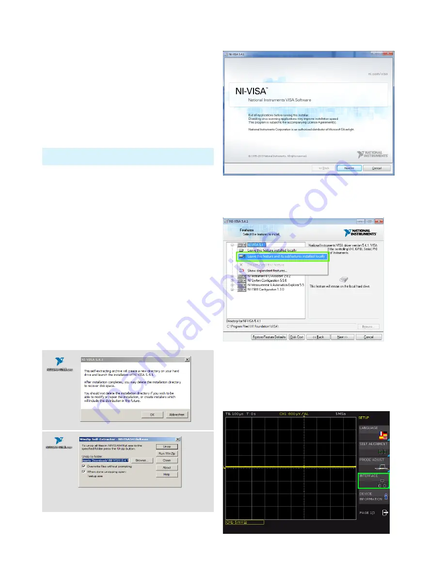
Below please find an example for NI-VISA 5.4.1:
The HMExplorer software does not support the communication
via USB TMC.
Fig. 14.1: NI-VISA 5.4.1
Select “Next“ to start the installation and follow the
installation instructions.
In this step, please select “NI-VISA xxx --> Leave this fea-
ture and its subfeatures installed locally“.
Now that you have successfully installed the NI-VISA
drivers, you can switch your R&S®HMO1002 resp.
R&S®HMO1202 to the USB-TMC interface. Select
the SETUP menu of your oscilloscope, and choose
INTERFACE.
Fig. 14.2: NI-VISA installation instructions
Fig. 14.3: NI-VISA feature installation locally
Fig. 14.4: Setup menu


