21
Horizontal System
by means of low memory depth (as is the case with other
manufacturers) it is nearly impossible to zoom in retros-
pectively in STOP mode.
5 .4 Interlace Mode
In interlace mode, ADC and storage of two channels are
connected. This doubles the sampling rate and the acquisi-
tion memory. A channel is considered active even if it has
been deactivated while still serving as the trigger source. If
a channel is activated, the respective LED next to the input
connector is illuminated. The following conditions must be
met to activate the Interlace mode:
❙
No active logic pod
❙
None of the serial or parallel buses are active
❙
Logic trigger not active
The interlace mode will be activated automatically.
5 .5 ZOOM Function
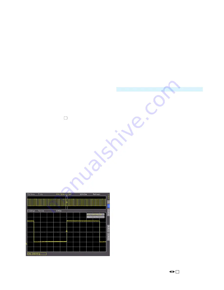
The R&S®HMO1002 resp. R&S®HMO1202 series features a
memory depth of 1 MSa resp. 2MSa. This allows the user
to record long and complex signals which can be analyzed
in full detail with the Zoom function. To activate this fea-
ture, press the ZOOM key
40
. The screen will be divided
into two sections. The upper window displays the entire
time base window whereas the lower graticule shows an
enlarged section of the upper window. The enlarged signal
section is marked by two blue cursors in the original signal
(upper window). If several channels are activated in Zoom
mode, all displayed channels will be zoomed simultane-
ously by the same factor and at the identical position. Fig.
5.5 displays the Zoom window with 100 µs per division.
The signal was captured within a time window of 12ms.
The zoom area (lower grid) also displays the parameter for
zoom time base whereas time is displayed above the zoom
window. Z indicates the zoom time base (zoom factor)
and determines the width of the zoom area displayed in
the zoom window (10 divisions x scaling per division). Tz
indicates the zoom time and determines the position of the
zoom area.
The time base setting in the upper right of the display is
highlighted in gray while the zoom time base above the
Fig. 5.5: Zoom function
zoom window is marked in white. The large knob in the
HORIZONTAL menu is used to change the zoom factor.
You can also press this knob. If the knob is pushed, the
time base setting is highlighted in white and the zoom time
base in gray. Now the knob is available to select the time
base setting. This allows you to change time base settings
without having to leave the zoom mode. Pressing the knob
again will highlight the cursors limiting the zoom area in
white, allowing you to use the knob to change the zoom
area. Now you can use the small knob in the horizontal
area of the control panel to move the position of the zoo-
med section across the entire signal. As described above,
pressing the large knob enables you to set the time base
but not the zoom factor. This in turn enables the small
knob to move the trigger position to define the relationship
of pre- and post captures/records.
In the acquisition mode ROLL, it is generally not possible
to zoom in on the memory because the signal values of
the X axis are always captured with the maximum memory
depth. The acquisition mode NORMAL always includes
more samples in the memory than what can be shown in
the display. That explains why in this mode you are able
to zoom in on the memory. The same does not apply to
the values in the Y axis (amplitude). These values apply to
a specified axis and can therefore also be scaled in ROLL
mode.
5 .6 Navigation Function
The X-POS. function (MENU key in the HORIZONTAL
section) offers easy trigger time handling and allows it
to be entered numerically. The soft menu keys allow you
to set the trigger time to the minimum or the maximum
value, for instance. You can use the soft menu key TIME
REFERENCE to define where in the signal window to find
the trigger point value “0”. The signal is scaled by this re-
ference point. You can use the universal knob in the CUR-
SOR/MENU section to select the desired setting.
5 .7 Marker Function
Markers allow you to highlight specific positions on the
screen, e.g. a rising or falling slope, an unexpected signal
value or a search result. Markers can be used to identify
specific signal sections to zoom in on and to analyze the
data more closely. Use the soft menu to activate the mar-
ker function. Press the MENU key in the HORIZONTAL
section to open the soft menu. Use the universal knob in
the menu to select MARKER. Once this mode is activated,
you can press the SET/CLR key to set a time marker at the
6th time unit (the menu in the center of the grid must be
deactivated). The time markers are marked by a vertical
line in gray-blue. The knob X Position allows you to move
the signal including the set marker. After identifying an
important signal position and setting it to the center of the
screen using the position knob, you can set an additional
marker. This procedure allows you to mark up to 8 interes-
ting positions within the signal. You can toggle between
markers by pressing the arrow keys
37
. These keys
The ZOOM function is not available in ROLL mode.


