44
Documentation, Storage and Recall
11.5 FILE/PRINT Key Definition
The FILE/PRINT key in the GENERAL section allows you
to save instrument settings, curves, screenshots and
screenshot settings simultaneously with just one key. As
described in previous chapters, you must first select the
corresponding settings for storage location, name etc.
The soft menu key FILE/PRINT in the SAVE/RECALL main
menu opens the setup menu for the FILE/PRINT key. You
may choose from the following actions:
❙
DEVICE SETTINGS:
Stores settings
❙
TRACES:
Stores curves
❙
SCREENSHOTS:
Stores screenshots
❙
SCREEN & SETUP:
Stores screenshots and settings
❙
PRINT:
Prints directly to a compatible printer (Postscript,
some PCL and PCLX capable printer)
If you press the respective soft menu key to activate the
required operation, the corresponding menu will be dis-
played with a blue background. Press the MENU OFF key
to quit the selection menu. If you press the FILE/PRINT
key, the selected function will be performed.
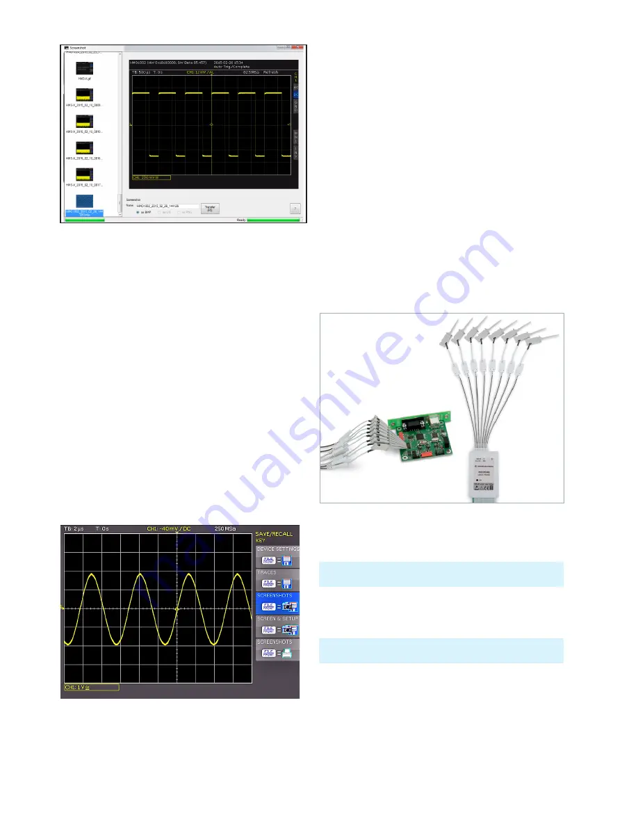
Fig. 11.7: Definition of FILE/PRINT key
Fig. 11.6: Screenshot module
12 Mixed-Signal
Operation
As a standard, the R&S®HMO1002 resp. R&S®HMO1202
series is equipped with the connectors for the
R&S®HO3508 logic probe to add 8 digital logic inputs. All
software required for the mixed signal operation is already
included in the firmware of the R&S®HMO1002 resp.
R&S®HMO1202 series. It is only necessary to purchase and
connect the active R&S®HO3508 logic probe (8 channels).
If you activate the POD on R&S®HMO1002 series, analog
channel 2 will be deactivated automatically. This only al-
lows the configuration of 1 analog c 8
logic chan-
nels on the screen simultaneously. The R&S®HMO1202
series allows the configuration of 2 analog ch 8
logic channels on the screen simultaneously.
12 .1 Logic Trigger for Digital Input
12 .2 Display Functions for the Logic Channels
To switch on the digital channels, press the POD key in the
VERTICAL section. The digital channels 0 to 7 will now dis-
play on the screen. For the logic channels, a logic „1“ will
be indicated by a bar that is two pixels wide, and a logic
„0“ will be indicated by a bar that is one pixel wide. The
set logic level and a figure which shows the logical states
will be shown next to the name POD in the information
field in the bottom left of the display.
Fig. 12.1: Optional logic probe R&S®HO3508
Please find an additional description of the logic trigger for the
inputs of the logic probe in chapter 6.3.3.
You must always set the level to distinguish between the logic
states (High/Low) in the VERTICAL MENU..


