


Basic Operations
R&S
®
ESRP
51
Getting Started 1316.4697.02 ─ 07
The icon on the tab label indicates that the displayed trace no longer
matches the current instrument settings. This may be the case, for example,
if a trace is frozen and the instrument settings are changed. As soon as a
new measurement is performed, the icon disappears.
To start a new channel
1. Click the icon in the toolbar at the top of the screen (see also
on page 58 on how to display the toolbar).
2. Select the softkey for the required measurement mode.
A new tab is displayed for the new channel.
6.1.2
Display of Hardware Settings
Information on hardware settings are displayed in the channel bar above the dia-
gram.
Invalid settings
A bullet next to the hardware setting indicates that user-defined settings are
used, not automatic settings. A green bullet indicates this setting is valid and
the measurement is correct. A red bullet indicates an invalid setting that
does not provide useful results.
It is the user's responsibility to remedy such a situation.
Editing settings in the channel bar
All settings that are displayed in the channel bar can easily be edited by
touching the setting in the display (with a finger or mouse pointer). The cor-
responding (edit) dialog box is displayed where you can edit the setting.
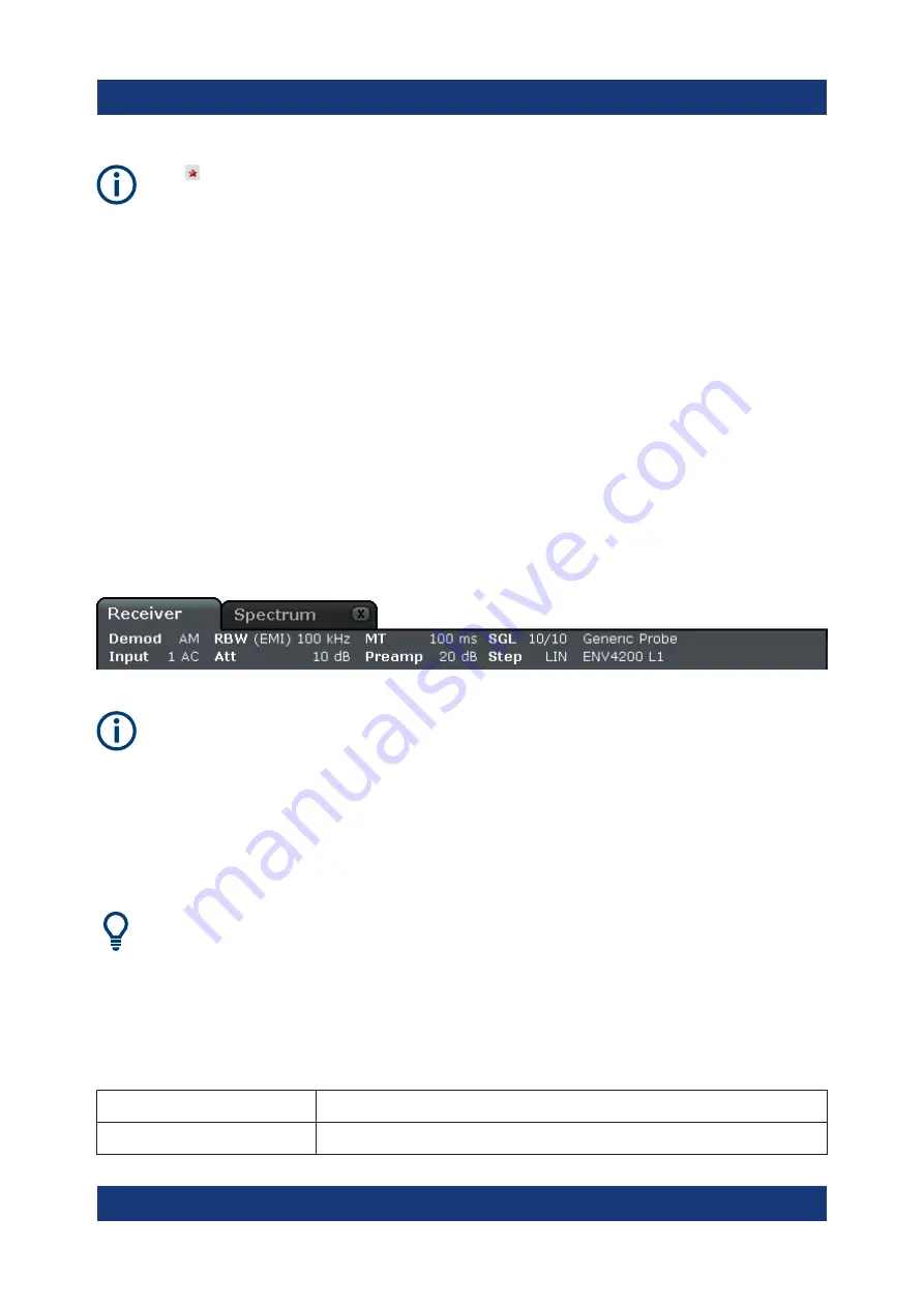
In receiver mode, the R&S
ESRP shows the following settings:
Demod
Active AF demodulation.
Input
Type of coupling currently used.
Information in the Diagram Area


