


39
6.16.3 Sump Breather
Inspect the sump breather element monthly. If the element is saturated it should be
replaced. A small amount of oil may be present in the housing outside the filter element;
this is normal and will drain back to the sump.
6.16.4 Control Air Filter
Inspect element monthly. Replace annually, or if saturated with condensate.
6.16.5 Engine Oil Filter
Similar in design to the Compressor Oil Filter, this filter should be changed with the
engine oil every 500 hours of service.
6.16.6 DEF Manifold Filter
A filter located inside of the DEF tank at the suction port of the pump.
6.16.7 Diesel Exhaust Fluid Filter
A secondary filter located on the exhaust aftertreatment system.
6.16.8 Fumes Disposal Filter Element
The filter for the open crankcase ventilation system (OCV) may be located toward the
front or toward the rear of the left side of the engine. A filter that has been used may
contain a small amount of engine oil.
6.16.9 Fuel System Primary/Secondary Filter (Water Separator) Element
Water in the fuel can cause the engine to run rough. Water in the fuel may cause an
electronic unit injector to fail. If the fuel has been contaminated with water, the element
should be changed before the regularly scheduled interval. The primary filter/water
separator also provides filtration in order to help extend the life of the secondary fuel
filter. The element should be changed regularly. The primary filter/water separator
should be changed at 50 to 70 kPa (15 to 20 inches Hg).
7. Standby and Stored Units
7.1. Standby Units
Back-up or stand-by compressors must be run weekly to assure that no condensation is
allowed to accumulate internally. When operated, a stand-by unit should be allowed to
reach full operating temperature for 30 minutes.
7.2. Short-term Storage
For storage intervals of one month or less, open the manual drains on the bottom of
automatic drain traps and run the unit fully loaded for 15 minutes. Drain water from the
Diesel fuel/water separator. In colder conditions approaching freezing temperatures, the
external connections for the heat trace and battery charger must be plugged in to an
120VAC external power source.
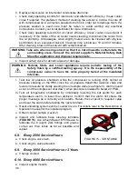
See FIGURE 6A/6B
for location of connections.