26
2.7. Air Receiver
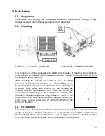
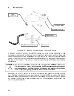
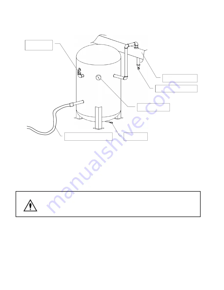
FIGURE 13 - TYPICAL AIR RECEIVER CONFIGURATION
A properly sized air receiver should be located as close to the discharge of the
compressor as possible, and before any air treatment accessories such as filters and
dryers. The piping from the compressor air outlet should be connected near the bottom
of the receiver and piping to the plant compressed air system should be connected near
the top of the receiver. The receiver must have provisions for draining accumulated
condensate.
WARNING:
The receiver must be equipped with an approved (ASME) safety valve.
The compressor owner is responsible for the proper sizing, installation,
and maintenance, and for periodic inspection and testing, of the safety
valve. A pressure gauge and drain valve are also required.
Generally, the receiver should be sized for a minimum of 2 gallons of storage for each
cubic foot per minute of compressor air delivery. The size of the air receiver will directly
affect the load cycle time of the compressor. Increasing the capacity of the air system
will result in fewer load cycles, reduced wear on the compressor components, and
improved system stability.
Flexible connection (hose)
Safety
relief valve
Drain valve
Pressure gauge
Drop leg with drain valve
Air system header


