


33
•
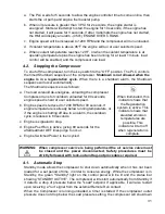
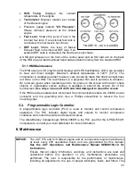
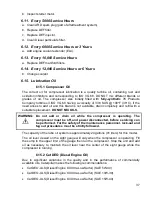
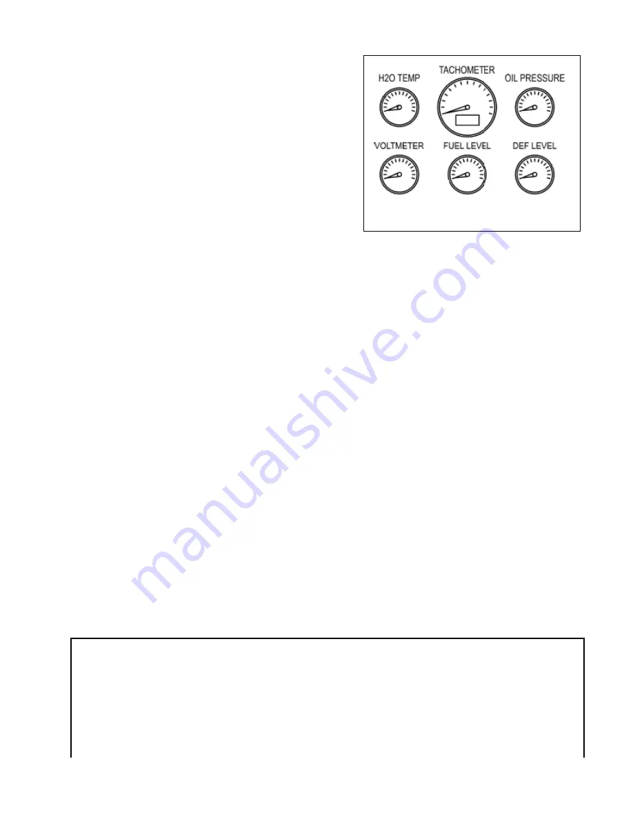
H2O Temp
: Displays the coolant
temperature of the engine.
•
Tachometer
: Displays rotation per minute
of the Diesel engine.
•
Pressure gauge marked "
Oil Pressure
":
Shows lubricant pressure at the Diesel
engine.
•
Fuel Level
: Shows the level of fuel in the
internal fuel tank. If an external fuel tank is
connected, the fuel level is not shown.
•
DEF Level
: Shows the level of Diesel
Exhaust Fluid in the internal DEF tank. If an
external DEF tank is connected, the fluid level is not shown.
A USB port extension on the front of the control panel and an SD card slot on the back
of the HMI are provided download trend data and alarm history from the standard HMI.
5.1.1 HMI Maintenance
The HMI uses an LCD (liquid crystal display) with LED backlighting. LCD’s are sensitive
to heat and direct sunlight. Maximum ambient temperature is 120
°
F (50
°
C). The
compressor is weather-resistant; however, care should be taken that direct sunlight does
not shine on the HMI. The touchscreen is a polyester film and is sensitive to abrasion.
Do not wear gloves when operating and do not press on the screen with hard or sharp
objects. A replaceable screen overlay is available to extend the service life of the
touchscreen.
Use only a clean soft cloth and mild detergent to clean the screen
.
If the HMI requires replacement, disconnect the communication cable, the 24VDC power
connector and the grounding wire. Use a Phillips screwdriver to remove the four
mounting clips.
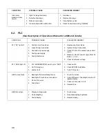
5.2. Programmable Logic Controller
A programmable logic controller (PLC) is used to monitor and control compressor
operations. The PLC includes digital inputs and outputs to monitor compressor
conditions and control the starter and solenoid valves.
The Allen-Bradley CompactLogix 5069-L306ER is the PLC used for the GPKD-1550-H
compressors. Consult your local distributor for more information.
6. Maintenance
NOTICE:
The CAT C15 and C18 Diesel engine and its components require maintenance
at least every 250 operational hours and are generalized for this manual.
See the CAT Operations and Maintenance Manual SEBU9106-14 for
instructions.
Ensure that all safety information, warnings, and instructions are read and
understood before any operation or any maintenance procedures are
performed. The user is responsible for the performance of maintenance,
including all adjustments, the use of proper lubricants, fluids, and filters. The
FIGURE 14 – AUX. GAUGES