background image


17 


E10037-180424 


PROBEX 

NOTE: 

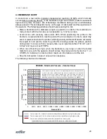
For a representative 

‘c’, the user must conduct numerous volume 

calibrations prior to testing and in the same environmental conditions. 
When delay between calibrations and testing exceeds two hours, 
kneading of the membrane should be repeated. Therefore, we suggest 
beginning each testing day by doing these calibrations, which takes 
more than an hour. 

The procedure to determine the volume correction is as follows: 

STEP 1.  Place the probe in the calibration tube. 

STEP 2.  Pressurize the probe up to 30 MPa. Maintain pressurize and record readings every 

minute during 15 minutes. During this time, the conical tip (A) must be removed, 
and the operator must check for leaks. If a leak is found, it should be fixed. Bring 
pressure and volume back to 0 and put the conical tip back in place.  

STEP 3.  Inflate the probe in increments of 3 MPa up to 30 MPa. At each step of pressure, 

record the corresponding volume displayed on the readout unit after one minute. 
Then deflate the membrane. 

STEP 4.  Repeat last step 2 times. At the end of the last loading, decrease pressure from 

30  to  15  MPa  and  then  back  to  30  MPa.  At  each  step  of  pressure,  record  the 
corresponding volume displayed on the readout unit after one minute. Then deflate 
the membrane. 

          Ensure that the last two calibrations are repeatable enough i.e. 

that ‘a’ does not 

vary by more than +/- 0.01 cm

3

 / MPa between 15 and 30 MPa. 


Checking for leakage


During volume calibration, it is important to make sure the equipment is properly saturated 
and that it is not leaking. This is done by visual inspection (no water is leaking out of the 
probe,  especially  next  to  the  probe  saturation  plug),  and  by  getting 

‘Delta  V  CC’ 

stabilizing between 3 & 4 cm

3

 / 3 MPa between 15 and 30 MPa. 


NOTE: 

After running calibrations, make sure that the ‘a’ measured between 15 
and 30 MPa is stable between 1 and 1.33 cm

/ MPa. 


2.5 

BOREHOLE 

-


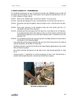
Core  borehole  to  the  deepest  testing  elevation.  In  weathered  rock,  it  might  be 
necessary to use t rotary drilling for achieving a tight hole. No percussion 
drilling  can  be  done.  Borehole  walls  yielded  with  this  method  are  not  smooth 
enough. 

-


Clean the borehole. No sand should settle around the probe during a test. 

-


Borehole walls must be smooth and as close as possible to 76 mm.  

-


Keep core samples available on site 

-


Try to reduce down time between drilling and testing, especially in soft rock


Summary of Contents for PROBEX

Page 1: ...sonnel Its misuse is potentially dangerous The Company makes no warranty as to the information furnished in this manual and assumes no liability for damages resulting from the installation or use of t...

Page 2: ...D TURNING ON DP BOX 8 2 2 4 USING THE DP BOX READER APPS 9 2 3 SATURATION OF THE PROBEX 15 2 4 CALIBRATION OF THE PROBEX 16 2 4 1 PRESSURE LOSS CALIBRATION 16 2 4 2 VOLUME LOSS CALIBRATION 16 2 5 BORE...

Page 3: ...core as well as cylinder E In order to inflate or deflate the PROBEX probe the manual hydraulic pump acts on the dual action hydraulic module The dual piston identified by letters F G and H is the mov...

Page 4: ...2 E10037 180424 PROBEX Schematic Representation of the PROBEX Potentiometer...

Page 5: ...ater side of the piston F is slightly larger than the area of the hydraulic oil side by a ratio of 95 5 this due to the area of rod G which represents 4 5 of the piston area The water pressure which a...

Page 6: ...d the deflation line a working pressure of 32 5 MPa 1 4READOUT UNIT The model DP BOX is a portable datalogger equipped with rechargeable batteries It directly provides the volume and pressure changes...

Page 7: ...k connects must be aligned for connection Then turn the ring to misalign the ball and the notch in order to prevent accidental disconnection when inflating the PROBEX This will prevent the PROBEX from...

Page 8: ...6 E10037 180424 PROBEX PROBEX Assembly Thread this end of tubing cable through sufficient number of casing lengths to reach maximum testing depth...

Page 9: ...n be uploaded to a laptop via USB communication The DP Box comes in a convenient water proof enclosure and is fitted with two 12 V rechargeable batteries providing over 8 hours of autonomy in normal c...

Page 10: ...om using the DP Box the DP Box READER Application should be installed on a Tablet This application can be downloaded from Roctest web site 2 2 3 CONNECTING AND TURNING ON DP BOX Connect the electrical...

Page 11: ...uetooth communication between the DP Box and the Tablet which will be confirmed when the DP box LED will blink quicker see below for more information 2 2 4 USING THE DP BOX READER APPS The DP Box Appl...

Page 12: ...the DP BOX which takes a few seconds The name of the DP Box will then replace the Scanning inscription Used for configuring and running a testing session Used for configuring and running a calibration...

Page 13: ...ument Add a New Instrument and Select the Type of instrument PROBEX and enter the serial number appearing on the control unit e g 003717003 The DP Box name should appear here Select for additional fun...

Page 14: ...ry calibration at the bottom of the screen Finally select this instrument Set the date and time of the Tablet if necessary Go in Quick Readings and press the green icon for reading the sensors Two typ...

Page 15: ...cted ID Once setup is completed select Begin Calibration or Test to start Once calibration or testing is started a window like the one below will be displayed After saving the initial readings the ope...

Page 16: ...select the specific file you want to see For starting the timer Readings are automatically recorded each time timer gets to zero Graph is plotted here Displays actual Pressure and Volume readings For...

Page 17: ...If so please contact Roctest 2 3SATURATION OF THE PROBEX An adequate water saturation of the PROBEX probe and cylinder E is necessary before using the equipment Sometime the probe is delivered pre sa...

Page 18: ...calibration must be done a single time when using a new membrane The procedure consists of STEP 1 Once the whole system is saturated place the probe horizontally at ground level next to the pump Infl...

Page 19: ...from 30 to 15 MPa and then back to 30 MPa At each step of pressure record the corresponding volume displayed on the readout unit after one minute Then deflate the membrane Ensure that the last two ca...

Page 20: ...al connections to the manual pump and readout unit and check that the whole system is working well by inflating and deflating the probe Check the battery charge STEP 5 Insert the PROBEX into the boreh...

Page 21: ...19 E10037 180424 PROBEX Methods Used for Lowering Probe in Place Slotted adapter NQ to AW Rods or BW Casing to NQ Rods...

Page 22: ...ve and strike the handle of the pump valve from position 1 to 2 Open slowly the cyclic valve for reducing pressure For increasing the pressure strike the handle of the pump back in the position 1 and...

Page 23: ...e V volume increase P Corrected pressure increase between P1 and P2 V Corrected volume increase between P1 and P2 Pressure and volume are corrected as follows P Pr Pl Pc Where P Corrected pressure Pr...

Page 24: ...to run a volume calibration after a test if the operator has any reason to believe that the factor c might have changed Volume of the probe at rest Vo Vo is theoretically 1950 cm3 considering the theo...

Page 25: ...ier is recommended The borehole needs to be very tight Finally de aired water should be used for reducing the deformation of the probe Additional information can be found in document 7 cited below 4 2...

Page 26: ...of bursting is high when the borehole is very large or when the tested material is very soft the operator should reduce the pressure increments to 2 1 or 0 5 MPa for instance in order to obtain maximu...

Page 27: ...away from the steel core It will slide on the O rings No 5 mounted at both ends of the steel core No 3 and the water contained in the annular space between the core and the membrane No 14 will flow o...

Page 28: ...SS PIECE Membrane Diameter With use the PROBEX membrane will deform in a plastic way resulting in a diameter increase This phenomenon will not invalidate test results but may prevent PROBEX insertion...

Page 29: ...ver 40 C However always keep the PROBEX out of direct sun The use of a canopy is ideal Try to avoid significant thermal changes on the probe If inevitable let the probe stabilize in temperature at the...

Reviews: