


MSR300 Safety System Manual
Rockwell Automation
MSR300 Manual.doc
Pg 34 of 85
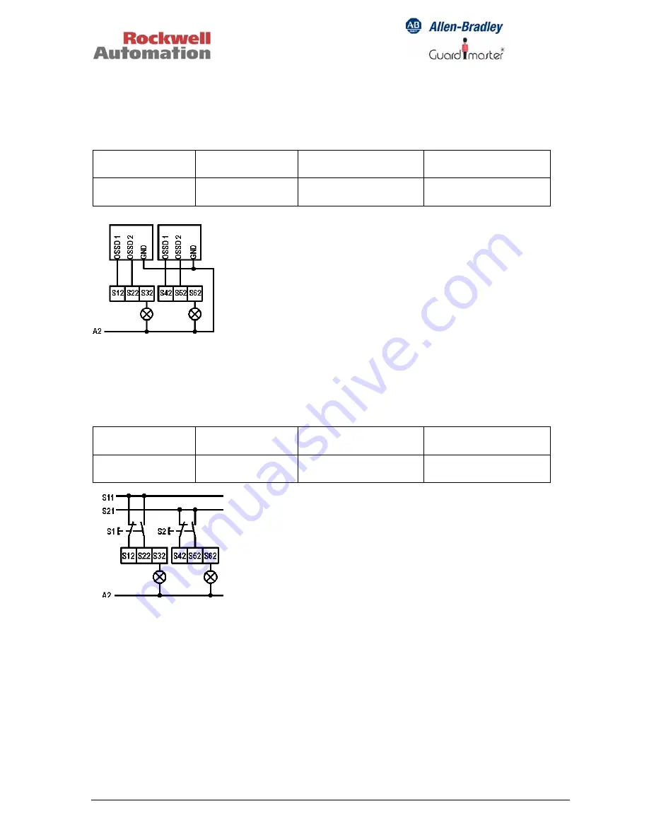
4.2.3.6 Light
Curtain
Switch setting: 6
Without simultaneity monitoring.
Input 1
Input 2
Solid-state auxiliary
output: Input 1
Solid-state auxiliary
output: Input 2
OSSD1-S12
OSSD2-S22
OSSD1-S42
OSSD2-S52
S32
S62
4.2.3.7 Two-hand
Control
Switch setting: 7
With simultaneity monitoring (0.5 second limit).
Input 1
Input 2
Solid-state auxiliary
output: Input 1
Solid-state auxiliary
output: Input 2
S11-S12: N/C
S11-S22: N/O
S21-S42: N/C
S21-S52: N/O
S32
S62