Rockwell Automation Allen-Bradley CENTERLINE 2500 Instruction Manual Download Page 56

Publication 2500-IN001A-EN-P - May 2006

6-4

        Unit Information

Connected

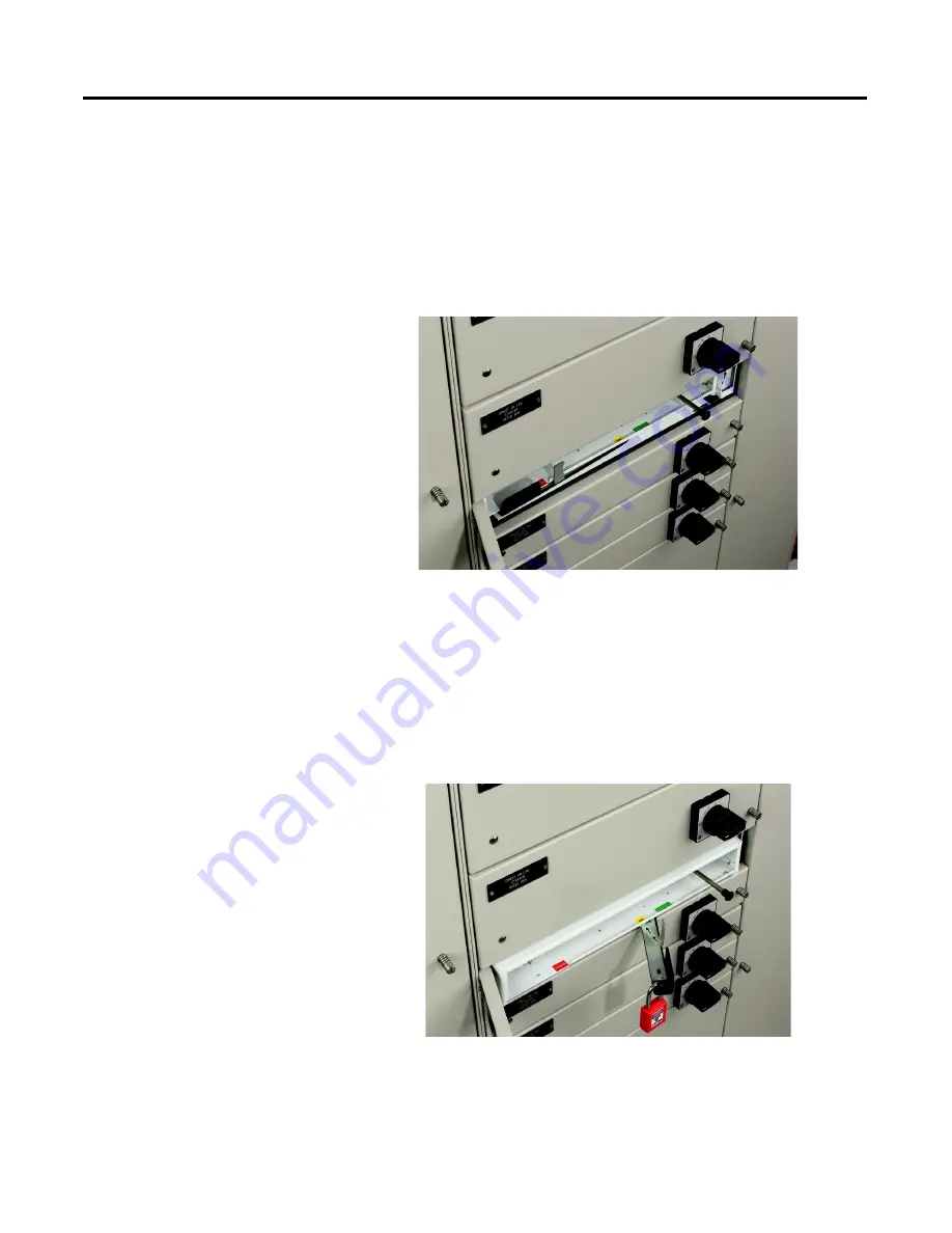
In the connected position, the line, load, control, network, and PE 
connections are engaged. Closing the unit door helps ensure that the withdraw 
lever is in the connected position. To engage the interlock or turn the branch 
circuit device to the ON/I position, the unit door must be fully closed.

Figure 6.6 Connected Position

Test

In the test position, the control, network, and PE connections are engaged. 
Line and load connections are isolated. This helps allow the control and 
network wiring of the units to be verified. Units can be locked in this position.

Figure 6.7 Test Position (Locked)

Summary of Contents for Allen-Bradley CENTERLINE 2500

Page 1: ...CENTERLINE 2500 Low Voltage Motor Control Centers Instruction Manual...

Page 2: ...ssume responsibility or liability for actual use based on the examples and diagrams No patent liability is assumed by Rockwell Automation Inc with respect to use of information circuits equipment or s...

Page 3: ...Instruction Manual CENTERLINE 2500 Motor Control Centers...

Page 4: ......

Page 5: ...Handling and Storage 2 2 Chapter 3 Installation of Columns Location Planning 3 1 Environment 3 1 Securing a Motor Control Center 3 2 Joining and Splicing 3 7 Torque Specifications 3 14 Chapter 4 Inst...

Page 6: ...wable Units 8 1 Removing the Unit Door 8 3 Chapter 9 Motor Control Center Options DeviceNet Motor Control Centers 9 1 Chapter 10 Maintenance Suggested Maintenance Guidelines 10 2 Chapter 11 Maintenanc...

Page 7: ...cables Control station Door mounted assembly that houses pushbuttons indicator lights and other small control devices Control unit Unit that contains any type of power control or metering device inclu...

Page 8: ...r Plating Type of surface treatment that distributes a layer of protective coating on structural parts Plug in units Replacable units with line connections made via unit bus line stabs Plug in units i...

Page 9: ...t Withdraw lever Mechanism used to insert and remove withdrawable units The withdraw lever is used to select an operating position inserted test disconnected and withdrawn and has mechanical detents t...

Page 10: ...Publication 2500 IN001A EN P May 2006 iv Notes...

Page 11: ...unit arrangement An optional 600 ampere vertical bus provides an effective rating of 1200 amperes CENTERLINE 2500 MCCs utilize units with a full complement of AC drives soft starters and other devices...

Page 12: ...are in mm Table 1 1 Column Width Total Column Width Unit Width Vertical Wireway Width 700 mm standard 500 mm 200 mm 800 mm 500 mm 300 mm 900 mm 500 mm 400 mm 1000 mm 500 mm 500 mm Table 1 2 Column De...

Page 13: ...al Wireway Closing Plates Left Side Plate Horizontal Power Bus Center End Closing Plate Bottom Horizontal Wireway Closing Plates Mounting Channels Bottom Plates Bottom Horizontal Wireway Cover Right U...

Page 14: ...Publication 2500 IN001A EN P May 2006 1 4 General Information Figure 1 4 Columns Installed in a Front Mounted Configuration Figure 1 5 Columns Installed in a Double Front Configuration...

Page 15: ...p to 110 kA Up to 50 kA 1 s Creepage Distances and Clearances Rated Impulse Withstand Voltage Uimp Material Group Overvoltage Category Pollution Degree 6 8 or 12 kV IIIa 175 CTI 400 3 Bus Material and...

Page 16: ...located on the interior of the bottom plate of the unit On fixed units the unit identification label is placed on the interior right side plate See Figure 1 7 for unit identification label informatio...

Page 17: ...ance CENTERLINE 2500 MCC columns can be installed or added as follows In non sequential order Addition of a single column add on column Addition of multiple columns add on lineup of columns Addition o...

Page 18: ...Publication 2500 IN001A EN P May 2006 1 8 General Information Notes...

Page 19: ...ood framing and sheeting surround the columns Heavy duty export packaging is not watertight waterproof or intended for long term storage Shipping Weights and Dimensions The dimensions and approximate...

Page 20: ...dth mm Weight 1 kg 1 Weights are for an average motor control center with 6 units Refer to the packing slip shipped with your MCC for an exact shipping weight Height mm Width mm Depth mm Front Mounted...

Page 21: ...o the shipping skid until delivered to its final installation area Storage CENTERLINE 2500 MCCs units and related equipment must be stored in a clean dry environment with ambient temperatures ranging...

Page 22: ...Publication 2500 IN001A EN P May 2006 2 4 Transporting Motor Control Centers Notes...

Page 23: ...of protection provided by the enclosure Environment CENTERLINE 2500 MCCs are designed to operate under the service conditions described in IEC 60439 1 Be aware that variations in temperature and relat...

Page 24: ...ol Center Documentation packages shipped with assembled MCCs include an MCC elevation drawing showing an MCC floor plan layout To secure a column to the foundation refer to the provided floor plan lay...

Page 25: ...CENTERLINE 2500 Motor Control Centers for handling guidelines Securing a Column or Shipping Block Two or three steel M12 bolts minimum Property Class 8 8 are required to properly fasten each MCC colu...

Page 26: ...fasten the rear of the MCC to the foundation Figure 3 3 4 For Double Front Configured Columns remove the bottom horizontal wireway closing plates and fasten the MCC to the foundation using the mounti...

Page 27: ...006 Installation of Columns 3 5 Figure 3 3 Alternative Mounting Arrangement Three point Configuration Dimensions are in mm 1400 561 561 138 642 642 58 69 82 18 600 44 513 438 234 6 29 FRONT Protective...

Page 28: ...3 6 Installation of Columns Figure 3 4 Mounting Arrangement Double Front Dimensions are in mm 700 561 69 18 1196 513 438 234 6 642 29 82 44 513 438 156 234 6 82 FRONT Protective Earth Conductor 8 Moun...

Page 29: ...d within a horizontal wireway or blank unit space A fluorescent pink removable label on the outside of the column designates the location PE splice kits are located in the bottom horizontal wireway fa...

Page 30: ...he top bottom and center end closing plates on the sides of the two columns that are to be joined Figure 3 6 Figure 3 6 Removal of Covers for Joining 3 Consider how cables will be routed to the MCC an...

Page 31: ...hed together Do not use hardware to draw cabinets together 6 Refer to Table 3 1 on page 3 14 for torque requirements 7 Secure the MCC to the floor referring to the procedure explained earlier in this...

Page 32: ...ure 3 8 2 Primary bus access is through the vertical wireway door In cases where additional access is required narrow wireway doors horizontal bus ratings greater than 3200 A secondary access is avail...

Page 33: ...ication 2500 IN001A EN P May 2006 Installation of Columns 3 11 Figure 3 8 Primary Power Bus Access through vertical wireway Figure 3 9 Secondary Power Bus Access Horizontal Bus Cover Horizontal Bus Co...

Page 34: ...resent the neutral bar 2 Tighten hardware to torque specifications Table 3 1 on page 3 14 Do not grease or lubricate hardware 3 Replace bus access covers and check that bolts and nuts are secure If un...

Page 35: ...plice bar The PE splice bar is secured to the end of the horizontal PE during shipping Figure 3 12 Figure 3 12 Locating the PE Splice Bar 2 Use the PE splice bar to join the horizontal PE of each colu...

Page 36: ...he interior right hand side plate of fixed units Table 3 1 Torque Requirements for Hardware Connections Harware Description Torque Incoming Line Lug Attachment Bolts M12 x 1 75 61 N m Horizontal Power...

Page 37: ...ay from the PE conductor to avoid damage Cable should be positioned so that bending is minimized and relative vertical alignment to incoming connections is maintained Refer to the documentation packag...

Page 38: ...the size number and type of conductor The following are guidelines for selecting lugs based on incoming line available short circuit current Icw Icw 50 000 amperes RMS symmetrical use mechanical scre...

Page 39: ...n Figure 4 1 glass fiber reinforced tape or glass filament tape is used The taping should be continuous from the point the cables enter the MCC to the point the cables are terminated It is important t...

Page 40: ...ted into the brace and tightened so that cables are held tightly in place Figure 4 3 Securing Cables with Hardwood A second form of hardwood brace not shown is a yolk type in which the cables are pass...

Page 41: ...mber of units and their corresponding voltage Current ratings Kilowatt ratings Types of circuits Fuse sizes Circuit breaker ratings and trip settings Other important data The itemized list could be mo...

Page 42: ...ipping component devices in the MCC ATTENTION To ensure the safety of personnel performing the pre energizing check make sure remote MCC power sources are disconnected and locked in the OFF O position...

Page 43: ...way between the top of the column and the incoming line compartment terminals In full column incoming line compartments 24 modules the cables should be braced every 300 mm if the system s available sh...

Page 44: ...13 Check timing relay settings as required 14 Vents and Fans A Check vents to help ensure they are free from obstructions B Check fans used for forced air cooling to help ensure the shaft rotates fre...

Page 45: ...tegrity Conduct this test using an insulation resistance megger tester with a potential of 500 1000 volts This megger test should be conducted phase to phase phase to PE and when applicable phase to n...

Page 46: ...energizing from the remote location is strongly recommended If the MCC main circuit breaker or disconnect switch cannot be energized from a remote location follow the procedure below De energize the...

Page 47: ...s and the start up procedure requires that the respective motors be jogged or inched temporarily disconnect the power factor correction capacitors For more information on power factor capacitors and M...

Page 48: ...Width Column Top Horizontal Wireway Bottom Horizontal Wireway Bottom Horizontal Wireway Unit Location Unit Data Serial Number Wiring Diagram Size or Amp Rating Description Full Load Current Overload...

Page 49: ...M FDS MAIN Fusible Disconnect Switch M LUG MAIN Line Lugs METER Metering Unit NCP Neutral Connection Plate NLD ControlNet to DeviceNet PLC Programmable Logic Controller DNPS DeviceNet Power Supply RV...

Page 50: ...ontrol Center Layout Worksheet MCC Name Number ___________________________________________________________ Unit Location Unit Data Serial Number Wiring Diagram Size or Amp Rating Description Full Load...

Page 51: ...ing 5 11 Table 5 D Megger Reading Recording Table MCC Name Number ___________________________________________________________ Date Circuit Unit Name Number Phase to Phase Phase to PE Phase to Neutral...

Page 52: ...Publication 2500 IN001A EN P May 2006 5 12 Commissioning Notes...

Page 53: ...Unit Descriptions CENTERLINE 2500 MCCs are available with many combinations of withdrawable and fixed units Refer to Table 6 1 for the number of stabs and maximum ampere rating of each unit size Table...

Page 54: ...nal features include a separate unit door and optional door mounted pilot devices The unit door can be closed and latched providing isolation when the unit is removed Pilot devices are housed in remov...

Page 55: ...t is in one of the four positions An interlock helps prevent the unit from being inserted or removed while the branch circuit device is in the ON I position Three or four pole stabs are provided to ma...

Page 56: ...connected position To engage the interlock or turn the branch circuit device to the ON I position the unit door must be fully closed Figure 6 6 Connected Position Test In the test position the contro...

Page 57: ...e column but connections are not present This is an isolated position Units can be locked in the maintenance position Figure 6 8 Disconnected Position Withdrawn Withdrawable units can be completely re...

Page 58: ...Slide the locking mechanism toward the withdraw lever 3 Rotate the withdraw lever to the desired position Mechanical detents are used to help ensure that a position is selected 4 Release the locking...

Page 59: ...he height from the floor to the center of the top handles must be checked for compliance Figure 7 1 Operator Handle Height Door Latches Latches are provided on each unit door to hold the door closed a...

Page 60: ...publication 21 341 950 which is available online at www rockwellautomation com literature Figure 7 3 Small Rotary Operator Handle OFF O Position Opening the Unit Door 1 Turn the operator handle to the...

Page 61: ...ely operated to open the unit door i e open the door of an energized unit Figure 7 4 Activating the Defeater Screw on Small Operator Handles 1 Release the door latches 2 Locate the defeater screw on t...

Page 62: ...the steps below 1 The operator handle will be in the TRIPPED T position Figure 7 5 2 Turn the handle to the OFF O position 3 After the fault has been corrected verify that it is safe to re energize th...

Page 63: ...tion To modify the operator handle to allow locking in the ON I position follow the procedure illustrated in Figure 7 7 Figure 7 7 Modification of the Small Operator Handle to Allow Locking in the ON...

Page 64: ...styles disconnect and circuit breaker For additional information see publication 40053 127 01 for disconnect handles and 40053 265 01 for circuit breaker handles which are available online at www rock...

Page 65: ...g the release mechanism down 4 Carefully open the unit door Figure 7 10 Opening and Closing Unit Doors with Large Rotary Operator Handles Closing the Unit Door 1 Ensure the operator handle is in the O...

Page 66: ...he unit door i e open the door of an energized unit 1 Release the door latches 2 Locate the defeater mechanism on the right side of the handle 3 Use a flat blade screwdriver to push the defeater mecha...

Page 67: ...f the fault has been determined and corrected see Chapter 11 Maintenance After Fault Condition To reset the circuit breaker follow the steps below 1 The operator handle will be in the TRIP position 2...

Page 68: ...Follow appropriate company safety procedures 1 Operator handle must be in the OFF O position 2 Pull the middle section of the handle toward you The lock opening will now be visible 3 Insert and secur...

Page 69: ...handle to allow locking in the ON I position remove the tab shown in Figure 7 14 Figure 7 14 Removing the Locking Tab Once the tab has been removed the door can be locked in the ON I position Figure...

Page 70: ...position A unit interlock is provided with each plug in unit Unit interlocks help prevent units from being removed from or inserted into a column while the operator handle is in the ON I position Unit...

Page 71: ...n when inserting units All busbars and the line sides of the inserted units are energized and contact with these parts can cause injury or death ATTENTION To avoid personal injury and damage to the un...

Page 72: ...inue to insert the unit into the column The unit will lock in the Test position 5 Slide the locking mechanism toward the withdraw lever again and rotate the withdraw lever to the Connected position In...

Page 73: ...a unit door must be removed utilize one of the following procedures If present door mounted control stations can be removed from the door and kept with the unit Before performing work on units or unit...

Page 74: ...for control wires unplug this connection before removing the unit Remove and or disconnect door mounted devices and wiring 3 To remove one module unit doors the unit must be removed from the column F...

Page 75: ...necessary at the ends of trunk lines to reduce reflections of the communication signals on the network Refer to Figure 9 1 and follow the steps below to install terminating resistors 1 Locate the term...

Page 76: ...end of the splicing cable will be plugged into the right DeviceNet port in the column to the left of the splice 3 Route the cable through the top horizontal wireway into the column to the right of the...

Page 77: ...st of checks and tests performed Condition of the equipment Any repairs and or adjustments made to equipment For maintenance regarding specific components such as circuit breakers contactors AC drives...

Page 78: ...sure Sides If severe corrosion or discoloration is evident replace the damaged components Identify the cause of damage and make necessary repairs 3 Contaminants ATTENTION Follow local codes and guidel...

Page 79: ...binding Check functions of the operator handles Check the defeater mechanisms on operator handles Replace broken deformed malfunctioning or badly worn parts assemblies 6 Locking Devices Check locking...

Page 80: ...pe and rated fuse that was originally furnished with the MCC 13 Fans and Cooling Devices Inspect blowers and fans for operation and damage Replace blowers and fans that have bent chipped or missing bl...

Page 81: ...ever and locking mechanism operate freely Check for easy movement of withdrawable units within the column Test the unit interlock function 18 Final Check Ensure withdrawable units are in the correct o...

Page 82: ...Publication 2500 IN001A EN P May 2006 10 6 Maintenance Notes...

Page 83: ...e MCC investigate the cause of the fault and thoroughly inspect equipment Make necessary repairs to units components and structures as required prior to re commissioning the equipment Replacement comp...

Page 84: ...Publication 2500 IN001A EN P May 2006 11 2 Maintenance After Fault Condition Notes...

Page 85: ...environmental considerations etc The total number of similar devices supplied as original equipment within the MCC Individual user policies governing spare parts Consideration should also be given to...

Page 86: ...Publication 2500 IN001A EN P May 2006 12 2 Renewal Parts Notes...

Page 87: ......

Page 88: ...Publication 2500 IN001A EN P May 2006 Copyright 2006 Rockwell Automation Inc All rights reserved Printed in the U S A...

Reviews: