


17
LINHA ALIMENTAÇÃO DE GÁS
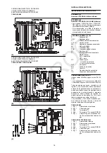
• A linha de gás está unida à ligação 1)(A), atra-
vés da flange 2), a junta 3) e os parafusos 4,
fornecidos com o queimador.
• A linha pode chegar pela direita ou pela
esquerda, conforme convenha. Ver Fig. (A).
• As electroválvulas 8)-9)(B) de gás devem
estar o mais perto possível do queimador,
para assegurar a chegada do gás ao cabeçal
de combustão no tempo de segurança de 2
segundos.
• Certificar-se de que o campo de taragem do
regulador de pressão (cor da mola) abarca a
pressão de gás de que necessita o queima-
dor.
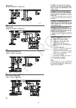
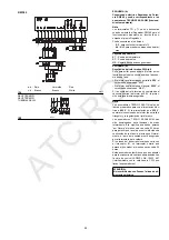
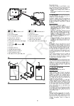
LINHA DE GÁS (B)
Está homologada conforme a norma EN 676 e é
fornecida em separado, com o número de
referência que é indicado na tabela (C).
LEGENDA (B)
1 - Conduta de chegada do gás
2 - Válvula manual
3 - Junta anti-vibratória
4 - Manómetro com válvula de botão
5 - Filtro
6 - Regulador de pressão
(vertical)
7 - Pressostato gás de mínima
8 - Electroválvula de segurança VS (vertical)
9 - Electroválvula de regulação VR (vertical)
Tem duas regulações:
• caudal de acendimento (abertura rápida)
• caudal máximo
(abertura lenta)
10 - Junta e flange, fornecidas com o queima-
dor
11 - Registo borboleta de gás
12 - Queimador
13 - Dispositivo para o controlo da estanqueci-
dade das electroválvulas 8)-9).
Conforme a norma EN 676, o controlo de
estanquecidade é obrigatório para queima-
dores com potência máxima superior a
1200 kW.
14 - Adaptador linha de gás-queimador
15 - Pressostato gás de máxima
P1 - Pressão no cabeçal de combustão
P2 - Pressão à saída do regulador
P3 - Pressão antes do filtro
L - Linha de gás fornecida em separado, com
o N° de Ref. que é indicado na tabela (C).
L1 - A cargo do instalador
LEGENDA TABELA (C)
13 = Dispositivo de controlo de estanqueci-
dade válvula VPS.
É fornecido à parte da linha de gás, por
encomenda.
Nota
Para a regulação da linha de gás, ver as ins-
truções que acompanham a mesma.
GAS LINE
• The gas train must be connected to the gas
attachment 1)(A), using flange 2), gasket 3)
and screws 4) supplied with the burner.
• The gas train can enter the burner from the
right or left side, depending on which is the
most convenient, see fig. (A).
• The gas solenoids 8)-9)(A) must be as close
as possible to the burner to ensure gas
reaches the combustion head within the safety
time range of 2 s.
• Make sure that the pressure governor calibra-
tion range (colour of the spring) comprises the
pressure required by the burner.
GAS TRAIN (A)
It is type-approved according to EN 676 Stand-
ards and is supplied separately from the burner
with the code indicated in Table (C).
KEY (A)
1 - Gas input pipe
2 - Manual valve
3 - Vibration damping joint
4 - Pressure gauge with pushbutton cock
5 - Filter
6 - Pressure governor
(vertical)
7 - Minimum gas pressure switch
8 - Safety solenoid
VS
(vertical)
9 - Adjustment solenoid
VR
(vertical)
Two adjustments:
• ignition delivery
(rapid opening)
• maximum delivery
(slow opening)
10 - Standard issue burner gasket with flange
11 - Gas adjustment butterfly valve
12 - Burner
13 - Gas valve 8)-9) leak detection control
device.
In accordance with EN 676 Standards, gas
valve leak detection control devices are
compulsory for burners with maximum out-
puts of more than 1200 kW.
14 - Gas train/burner adaptor
15 - Maximum gas pressure switch
P1 - Pressure at combustion head
P2 - Pressure down-line from the pressure gov-
ernor
P3 - Pressure up-line from the filter
L - Gas train supplied separately with the code
indicated in table (C)
L1 - The responsibility of the installer
KEY TO TABLE (C)
13 = VPS valve leak detection control device.
Supplied separately from gas train on
request.
Note
See the accompanying instructions for the
adjustment of the gas train.
ATC
ROC
Summary of Contents for TECNO 28-GM
Page 39: ...A T C R O C...


