


11
PRESSÃO DO GÁS
As tabelas existentes na margem indicam as
perdas de carga mínimas da linha de alimenta-
ção de gás em função da potência máxima do
queimador.
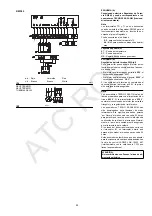
Coluna 1
Perda de carga cabeçal de combustão.
Pressão do gás na toma 1)(B), com:
• Câmara de combustão a 0 mbar
• Queimador funcionando na máxima potência
• A = Disco do gás 2)(B)p.14 regulado como é
indicado no gráfico (C)p.14.
• B = Disco do gás 2)(B) regulado a zero.
Coluna 2
Perda de carga registo borboleta gás 2)(B) com
abertura máxima: 90°.
Coluna 3
Perda de carga rampa de gás 3)(B) compreen-
de: válvula de regulação VR, válvula de segu-
rança VS (ambas com a máxima abertura),
regulador de pressão R, filtro F.
Os valores indicados nas tabelas referem-se a:
gás natural G 20 PCI 10 kWh/Nm
3
(8,6 Mcal/Nm
3
)
Com:
gás natural G 25 PCI 8,6 kWh/Nm
3
(7,4 Mcal/Nm
3
)
multiplicar os valores das tabelas por 1,3.
Para conhecer a potência MÁX aproximada à
que está a funcionar o queimador:
- Subtrair à pressão do gás na toma 1)(B) a
sobrepressão da câmara de combustão.
- Procurar na tabela relativa ao queimador con-
siderado, coluna 1A ou B, o valor da pressão
mais próxima ao resultado obtido na subtrac-
ção.
- Ler à esquerda a potência correspondente.
Exemplo - TECNO 28-GM:
• Funcionamento à MÁX potência
• Gás natural G 20 PCI 10 kWh/Nm
3
• Disco do gás 2)(B)p.14 regulado como é indi-
cado no gráfico (C)p.14
• Pressão do gás na toma 1)(B)
= 6 mbar
• Pressão na câmara de combustão = 2 mbar
6 - 2 = 4 mbar
À pressão de 4 mbar, coluna 1A, corresponde
na tabela do TECNO 28-GM uma potência MÁX
de 210 kW.
Este valor serve como primeira aproximação; o
real determinar-se-á através do contador.
Pelo contrário, para conhecer a pressão do gás
necessária na toma 1)(B), uma vez fixada a
potência MÁX à qual se deseja que o queima-
dor funcione:
- Procurar a potência mais próxima ao valor
desejado, na tabela relativa ao queimador
que se considere.
- Ler à direita, coluna 1A ou B, a pressão na
toma 1)(B).
- Somar a este valor a sobrepressão estimada
na câmara de combustão.
Exemplo - TECNO 28-GM:
• Potência MÁX desejada: 210 kW
• Gás natural G 20 PCI 10 kWh/Nm
3
• Disco do gás 2)(B)p.14 regulado como é indi-
cado no gráfico (C)p.14
• Pressão do gás à potência de 210 kW, na
tabela do TECNO 28-GM,
coluna 1A
= 4 mbar
• Pressão na câmara de combustão = 2 mbar
4 + 2 = 6 mbar
pressão necessária na toma 1)(B).
GAS PRESSURE
The adjacent tables show minimum pressure
losses along the gas supply line depending on
the maximum burner output operation.
Column 1
Pressure loss at combustion head.
Gas pressure measured at test point 1)(B), with:
• Combustion chamber at 0 mbar
• Burner operating at maximum output
• A = Gas ring 2)(B)p.14 adjusted as indicated
in diagram (C)p.14
• B = Gas ring 2)(B) adjusted to zero.
Column 2
Pressure loss at gas butterfly valve 2)(B) with
maximum opening: 90°.
Column 3
Pressure loss of gas train 3)(B) includes: adjust-
ment valve VR, safety valve VS (both fully open),
pressure governor R, filter F.
The values shown in the various tables refer to:
natural gas G 20 PCI 10 kWh/Nm
3
(8,6 Mcal/Nm
3
)
With:
natural gas G 25 PCI 8,6 kWh/Nm
3
(7,4 Mcal/Nm
3
)
multiply tabulated values by 1,3.
Calculate the approximate maximum output of
the burner thus:
- subtract the combustion chamber pressure
from the gas pressure measured at test point
1)(B).
- Find the nearest pressure value to your result
in column 1A or B of the table for the burner in
question.
- Read off the corresponding output on the left.
Example - TECNO 28-GM:
• Maximum output operation
• Natural gas G 20 PCI 10 kWh/Nm
3
• Gas ring 2)(B)p.14 adjusted as indicated in
diagram (C)p.14
• Gas pressure at test point 1)(B)
= 6 mbar
• Pressure in combustion chamber
= 2 mbar
6 - 2 = 4 mbar
A maximum output of 210 kW shown in Table
TECNO 28-GM corresponds to 4 mbar pres-
sure, column 1A.
This value serves as a rough guide, the effective
delivery must be measured at the gas meter.
To calculate the required gas pressure at test
point 1)(B), set the maximim output required
from the burner operation:
- find the nearest output value in the table for
the burner in question.
- Read off the pressure at test point 1)(B) on
the right in column 1A or B.
- Add this value to the estimated pressure in
the combustion chamber.
Example - TECNO 28-GM:
• Required burner maximum output operation:
210 kW
• Natural gas G 20 PCI 10 kWh/Nm
3
• Gas ring 2)(B)p.14 adjusted as diagram
(C)p.14
• Gas pressure at burner output of 210 kW, taken
from table TECNO 28-GM,
column 1A
=
4 mbar
• Pressure in combustion chamber
= 2 mbar
4 + 2 =
6 mbar
pressure required at test point 1)(B).
ATC
ROC
Summary of Contents for TECNO 28-GM
Page 39: ...A T C R O C...


