background image

19


MAIN DEVICES DESCRIPTION

x1

x1

A525454507

SMART SHOWER cable de alimentación 1m.

x1

A525454600

SMART SHOWER panel

x1

x1

A523887007

SMART SHOWER caja empotrada

x2

x1

x1

x1

A525907607

A553080707

SMART SHOWER cable panel 3m.

x1

A525454807

SMART SHOWER fuente
de alimentación 12V

x2

A525567103

Enlace recto con antirretorno
y filtro

Manual instalación

A525454707

SMART SHOWER módulo WIFI/BT

A525907507

SMART SHOWER mezclador de 3 vías

A553080807

Guía de usuario

x1

A523010907

Etiqueta control final

Regleta de conexión 

(

*

)

 SMART SHOWER Cable panel 10 m. disponible por separado en recambios (A525991207).

(

*

)

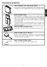
SMART SHOWER 3 WAY ELECTRONIC MIXER

Smart electronic device with digital readout and precise thermosta­
tic regulation of water temperature and flow at consumption outlets.

x1

x1

A525454507

SMART SHOWER cable de alimentación 1m.

x1

A525454600

SMART SHOWER panel

x1

x1

A523887007

SMART SHOWER caja empotrada

x2

x1

x1

x1

A525907607

A553080707

SMART SHOWER cable panel 3m.

x1

A525454807

SMART SHOWER fuente
de alimentación 12V

x2

A525567103

Enlace recto con antirretorno
y filtro

Manual instalación

A525454707

SMART SHOWER módulo WIFI/BT

A525907507

SMART SHOWER mezclador de 3 vías

A553080807

Guía de usuario

x1

A523010907

Etiqueta control final

Regleta de conexión 

(

*

)

 SMART SHOWER Cable panel 10 m. disponible por separado en recambios (A525991207).

(

*

)

SMART SHOWER PANEL 

Panel designed to be installed with the Roca thermostatic electronic 
mixer. It shows the temperature and flow controls, temperature va­
lues   (ºC), flow values   (l / min), safety temperature (38 ° C), programs, 
active output, alarms and errors. All preset parameters in the panel 
can be customized.
The panel executes the SMART SHOWER mixer programs, such 
as the Start up program, the preheating, cleaning programs or the 
disinfection program.

x1

x1

A525454507

SMART SHOWER cable de alimentación 1m.

x1

A525454600

SMART SHOWER panel

x1

x1

A523887007

SMART SHOWER caja empotrada

x2

x1

x1

x1

A525907607

A553080707

SMART SHOWER cable panel 3m.

x1

A525454807

SMART SHOWER fuente
de alimentación 12V

x2

A525567103

Enlace recto con antirretorno
y filtro

Manual instalación

A525454707

SMART SHOWER módulo WIFI/BT

A525907507

SMART SHOWER mezclador de 3 vías

A553080807

Guía de usuario

x1

A523010907

Etiqueta control final

Regleta de conexión 

(

*

)

 SMART SHOWER Cable panel 10 m. disponible por separado en recambios (A525991207).

(

*

)

SMART SHOWER CONCEALED BOX 

Plastic box to conceal in wall, to house the Smart Shower panel.

x1

x1

A525454507

SMART SHOWER cable de alimentación 1m.

x1

A525454600

SMART SHOWER panel

x1

x1

A523887007

SMART SHOWER caja empotrada

x2

x1

x1

x1

A525907607

A553080707

SMART SHOWER cable panel 3m.

x1

A525454807

SMART SHOWER fuente
de alimentación 12V

x2

A525567103

Enlace recto con antirretorno
y filtro

Manual instalación

A525454707

SMART SHOWER módulo WIFI/BT

A525907507

SMART SHOWER mezclador de 3 vías

A553080807

Guía de usuario

x1

A523010907

Etiqueta control final

Regleta de conexión 

(

*

)

 SMART SHOWER Cable panel 10 m. disponible por separado en recambios (A525991207).

(

*

)

SMART SHOWER WIFI/BT MODULE 

WIFI/BT module designed to connect the 3­way Smart Shower 
electronic mixer with a mobile application, to adjust the settings 
and obtain hydraulic information.

SMART SHOWER POWER SUPPLY 

Powers the entire SMART SHOWER system at 12V.

English

Summary of Contents for A5A104AC00

Page 1: ...SMART SHOWER ES EN A5A104AC00 ...

Page 2: ...2 Español ...

Page 3: ...SITIVOS PRINCIPALES 4 LISTA DE COMPONENTES 5 DIMENSIONES 6 ESPECIFICACIONES TÉCNICAS 7 CONSEJOS DE INSTALACIÓN 8 DESCRIPCIÓN GENERAL DE LA CONEXIÓN 9 AJUSTES DE FÁBRICA 9 EJEMPLOS DE INSTALACIÓN 10 GUÍA DE INSTALACIÓN 12 PRIMERA CONFIGURACIÓN 15 ...

Page 4: ... y caudal valores de temperatu ra ºC valores de caudal l min temperatura de seguridad 38 C progra mas salida activa alarmas y errores Todos los parámetros preestablecidos en el panel se pueden personalizar El panel ejecuta los programas de la SMART SHOWER mezclador como el programa Start up los programas de precalentamiento limpieza o el pro grama de desinfección x1 x1 A525454507 SMART SHOWER cabl...

Page 5: ... SMART SHOWER cable panel 3m x1 A525454807 SMART SHOWER fuente de alimentación 12V x2 A525567103 Enlace recto con antirretorno y filtro Manual instalación A525454707 SMART SHOWER módulo WIFI BT A525907507 SMART SHOWER mezclador de 3 vías A553080807 Guía de usuario x1 A523010907 Etiqueta control final Regleta de conexión SMART SHOWER Cable panel 10 m disponible por separado en recambios A525991207 ...

Page 6: ...2 64 238 32 64 275 257 SMART SHOWER mezclador 3 vías SMART SHOWER caja empotrada SMART SHOWER panel SMART SHOWER fuente alimentación SMART SHOWER módulo WIFI BT 70 5 70 5 80 27 Ø10 6 150 35 300 300 53 128 52 270 12 HOT COLD CONN 3 OUT 1 OUT 2 OUT 3 15 Español ...

Page 7: ...e control óptimo agua mezclada 32º C 50º C A partir de la fuente de alimentación AC DC suministrada con el producto Utilice solo esta fuente de alimentación SMART SHOWER panel GENERAL Condiciones ambientales Mínima Máxima Tecnología Capacitiva rotativa Temperatura ambiente 5 C 60 C Potencia máxima 1 5 W máxima Humedad relativa 30 95 Tensión nominal de alimentación 12 V DC Versión módulo HW 32 XX S...

Page 8: ...entradas de agua fría y caliente incluidos en el producto Purgue los tubos antes de realizar la instalación de la mezcladora y los accesorios de salida seleccionadas Ver guia de instalación en la página 12 Cuando finalice la instalación debe comprobar que todas las conexiones sean estancas Los cables empotrados en las paredes deben protegerse con tubos corrugados para per mitir su mantenimiento o ...

Page 9: ...alimentación con conector 1m 5 Módulo WIFI BT 6 Fuente de alimentación 7 Válvulas antirretorno x2 G1 2 filtros G 3 4 8 Regleta de conexión AJUSTES DE FÁBRICA La configuración de fábrica habilita solo una salida El programa Start up debe ejecutarse una vez que el sistema esté completamente instalado para habilitar salidas adicionales consulte la guía de usuario GENERAL Tiempo de pausa 3 min SALIDAS...

Page 10: ...N 1200 2 1 2 1 3 Min 200 HOT COLD 3 1200 2 OUT 1 OUT 2 1 TAPAR SALIDA 3 1200 HOT COLD 1200 OUT 1 1 TAPAR SALIDAS 2 Y 3 1 SALIDA 3 SALIDAS OUT 1 OUT 2 OUT 3 HOT COLD HOT COLD HOT COLD 2 SALIDAS HOT COLD HOT COLD HOT COLD Español ...

Page 11: ...sección D Instalar caja mezcladora módulo WIFI BT y fuente de alimentación en falso techo Distancia mínima entre módulo WIFI BT y usuario 200mm 25A lDn 0 03A 10 ó 15A Según normativa vigente L max 3m C A B 2 x 1mm2 L Min 300 mm ØMin 6 mm ØMax 8 5 mm La mezcladora debe instalarse fuera de los volúmenes V0 y V1 La fuente de alimentación y la conexión eléctrica deben ubicarse fuera de los volúmenes V...

Page 12: ... tuberías abriendo las llaves de corte individual de las alimentaciones 3 257 184 4 Gire los pies en la mezcladora premontados y fijar la a la pared o al techo con los tornillos apropiados Instale los filtros y válvulas antiretorno a las alimen taciones de la mezcladora Conecte las salidas de agua considerando que la salida1 OUT1 siempre debe estar activa se reco mienda asociarla al rociador super...

Page 13: ...l conector marca do como CONN2 Prepare la pared para la instalación de la caja empo trada del Panel Smart Shower y el tubo coarrugado para pasar el cable de señal tomando como refe rencia el dibujo dimensional TOP VIEW 7 TOP VIEW 8 Con la ayuda de un retractor de cable pase el cable del panel Smart Shower A525907607 a través del conducto Perfore la caja empotrable y pase el cable a través de la mi...

Page 14: ... el panel A525454600 en la caja de montaje TOP VIEW 11 1 3 2 1 5 POWER 12 CONN 1 CONN 2 HOT COLD OUT 1 OUT 2 OUT 3 CONN 3 12 Vdc Presione la parte superior y sujete la parte inferior con los tornillos suministrados Conecte el cable de alimentación 1m A525454507 POWER a la Mezcladora utilizando el conector marcado como CONN 3 12 Vdc Español ...

Page 15: ...imentación A525454807 Cable de 12V colores Blanco Blanco o negro Rojo Negro Instalación fija Marrón Azul Marrón Azul IMPORTANTE Conecte el cable de la fuente de alimentación a la fuente de alimentación A525454807 Se recomienda encarecidamente proteger la fuente de alimentación y Mezcladora contra el agua situán dolas en un lugar seco Español ...

Page 16: ...ma 2 Elija uso privado hogar y hasta 3 usuarios o público hoteles por ejemplo Privado Público Modo de ducha 3 A continuación se muestran las siguientes pantallas de información Recuerda realizar el Startup antes de empezar a usar tu ducha Puedes mejorar tu experiencia de ducha descargando la app Smart Shower Español ...

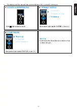
Page 17: ...MA Girar selector para resaltar SISTEMA y tocar 3 ELEGIR FUNCIÓN Girar selector para resaltar START UP y tocar Start up Limpieza Desinfección ACCEDER AL MENÚ PRINCIPAL Tocar para acceder al menú Usuarios Configuración Sistema Start up El sistema verifica las salidas para analizar el flujo y presión del agua ...

Page 18: ...IN DEVICES DESCRIPTION 19 COMPONENT LIST 20 DIMENSIONS 21 TECHNICAL SPECIFICATIONS 22 INSTALLATION TIPS 23 CONNECTION OVERVIEW 24 FACTORY SETTINGS 24 INSTALLATION EXAMPLES 25 INSTALLATION GUIDELINES 27 FIRST CONFIGURATION 30 ...

Page 19: ...emperature and flow controls temperature va lues ºC flow values l min safety temperature 38 C programs active output alarms and errors All preset parameters in the panel can be customized The panel executes the SMART SHOWER mixer programs such as the Start up program the preheating cleaning programs or the disinfection program x1 x1 A525454507 SMART SHOWER cable de alimentación 1m x1 A525454600 SM...

Page 20: ...10907 Installation manual User guide Final control label SMART SHOWER power supply cable 1m SMART SHOWER panel SMART SHOWER concealed box SMART SHOWER panel cable 3m Strip connector SMART SHOWER WIFI BT module SMART SHOWER 3 way mixer SMART SHOWER power supply 12V Check valve straight link filter Available in spare parts SMART SHOWER Cable panel 10 m A525991207 English ...

Page 21: ...2 64 238 32 64 275 257 70 5 70 5 80 27 Ø10 6 150 35 300 300 53 128 52 270 12 HOT COLD CONN 3 OUT 1 OUT 2 OUT 3 15 SMART SHOWER 3 ways mixer SMART SHOWER panel concealed box SMART SHOWER panel SMART SHOWER WIFI BT module SMART SHOWER power supply 50 English ...

Page 22: ...range 5º C 28º C Mixed water l min 6 22 Optimum control range mixed water 32º C 50º C With provided AC DC power supply unit Use only this power supply unit SMART SHOWER PANEL General Environmental conditions Minimum Maximum Technology Capacitive rotative Ambient temperature 5 C 60 C Maximum load 1 5 W maximum Relative humidity 30 95 Rated Impulse voltage 12 V DC Module version HW 32 XX SW 1 0rXXX ...

Page 23: ...he filters and non return valves must be installed in the cold and hot water inlets included in the product Purge the pipes before installing the mixer and the selected outlet fittings See instalation guidelines on page 27 When the installation is finished you must check that all connections are tight The cables embedded in the walls must be protected with corrugated pipes to allow main tenance or...

Page 24: ...ielded cable with connector 1m 5 WIFI BT module 6 Power supply 7 Check valves x2 G1 2 filters G 3 4 8 Strip connector FACTORY SETTINGS Default factory settings enable only one outlet Start up Program must be run once the system is completely installed to enable additional outlets check user guide GENERAL Pause timer 3 min FLOW RATE Factory default flow rate 12 L min OUTLETS Factory default Outlet ...

Page 25: ...PLES 1200 2 1 2 1 3 Min 200 HOT COLD 3 1200 2 OUT 1 OUT 2 1 TAP OUT 3 1200 HOT COLD 1200 OUT 1 1 TAPS OUT 2 OUT 3 1 OUTLET 3 OUTLETS OUT 1 OUT 2 OUT 3 HOT COLD HOT COLD HOT COLD 2 OUTLETS HOT COLD HOT COLD HOT COLD English ...

Page 26: ...vely dedicated to the Smart Shower D It is recommended to install mixer box WIFI BT module and power supply in false ceiling Minimum distance between WIFI BT module and user 200mm 25A lDn 0 03A 10 ó 15A L max 3m C A B 2 x 1mm2 L Min 300 mm ØMin 6 mm ØMax 8 5 mm Included 600 2250 600 V2 V3 V1 V0 D Recommended location Mixer WIFI BT module and power supply V Volume Mandatory According to current leg...

Page 27: ... purge the pipes opening the in dividual cut off valves of the supplies 3 257 184 4 Turn the feet on the mixer preassembled and se cure it to the wall or ceiling with the appropriate screws Install the filters and non return valves to the mixer feeds Connect the water outlets considering that output1 OUT1 must always be active it is recommended to associate it with the upper sprinkler Turn on the ...

Page 28: ... the connector marked CONN2 Prepare the wall for the installation of the recessed box of the Smart Shower Panel and the corrugated tube to pass the signal cable taking as reference the dimensional drawing TOP VIEW 7 TOP VIEW 8 With the help of a cable retractor run the Smart Shower A525907607 panel cable through the con duit Drill through the flush box and route the cable through it Attach the flu...

Page 29: ...o the interface Place panel A525454600 in the mounting box TOP VIEW 11 1 3 2 1 5 POWER 12 CONN 1 CONN 2 HOT COLD OUT 1 OUT 2 OUT 3 CONN 3 12 Vdc Press the top and secure the bottom with the supplied screws Connect the power cable 1m A525454507 POWER to the Mixer using the connector marked CONN 3 12 Vdc English ...

Page 30: ...e or black Red Black Fixed installation 8 6 8 Brown Blue Brown Blue MPORTANT Connect the power supply cable to the power supply A525454807 It is highly recommended to protect the power supply and Mixer against water placing them in a dry zone FIRST CONFIGURATION 1 Choose the desired language for the user interface English 中文 Español Selección de idioma English ...

Page 31: ...ower experience downloading the app Smart Shower 4 The system verifies the outputs to analyze the flow and pressure of the water 1 ACCESS MAIN MENU 2 HIGHLIGHT MAINTENANCE Tap to access menu list Turn knob to highlight MAINTENANCE then tap 3 CHOOSE FUNCTION Users Settings Maintenance Turn knob to highlight desired function then tap Start up Cleaning Disinfection Start up The system checks the outl...

Page 32: ...A553080707i Roca Sanitario S A Avda Diagonal 513 08029 Barcelona SPAIN www roca com ...

Reviews: