TECE TECEplanus, Technical Manuallines
TECE TECEplanus is a revolutionary product designed to simplify your plumbing installations. Our comprehensive Technical Manual provides detailed instructions, diagrams, and step-by-step guidelines, ensuring seamless installation and maintenance. Download our free manual today from manualshive.com and master the art of efficient plumbing with TECE TECEplanus.
Share
Download


Reviews:
No comments
Related manuals for TECEplanus
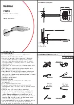
6068
Brand: Ca'Bano Pages: 4

SF1
Brand: rada Pages: 36

KV-5130
Brand: baliv Pages: 36

26637400
Brand: Hans Grohe Pages: 20

AVANTGARDE DJ2L/AVIV
Brand: SANPLAST Pages: 32

DELUXE HEALTH
Brand: Sunshower Pages: 13

Satellites Metis
Brand: Triton Pages: 25

Cayo series
Brand: Riobel Pages: 2

STRYKE T47766-FL
Brand: Delta Pages: 8

Cera Duo
Brand: Mora armatur Pages: 3

AXOR Montreux 16530 Series
Brand: Hans Grohe Pages: 173

1030-5103
Brand: Newport Brass Pages: 3

A81105A
Brand: imex Pages: 13

HANSAFIT 6504 2203
Brand: Hansa Pages: 28

EX18
Brand: Lacava Pages: 9

Optima
Brand: Hansa Pages: 32

K-8802
Brand: Kohler Pages: 12

K-73081
Brand: Kohler Pages: 48


