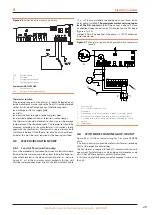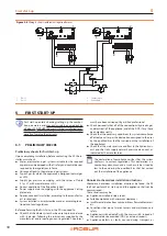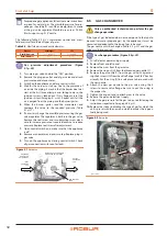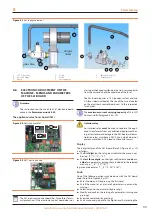
First start-up
32
5
For propane gas appliances, follow the same instructions
as given for natural gas. The manifold pressure for pro-
pane gas should be 5.1 inch WC and adjustment is made
at the gas valve regulator. Manifold pressure at 95.500
Btu/hr input using 0.14” nozzle.
The following Table 5.2
p. 32 summarizes nozzles and mani-
fold pressures for different types of gases.
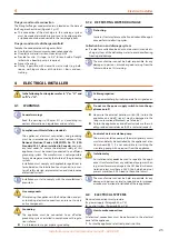
Table 5.2
Manifold pressure and nozzle diameter
Gas type
natural gas
LPG
Manifold pressure
2.77 inch WC
5.1 inch WC
Nozzle diameter
0.21”
0.14”
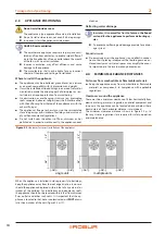
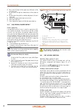
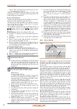
Gas pressure adjustment procedure (Figure
5.1
1.
Turn main gas valve knob to the "OFF" position.
2.
Remove the plug on outlet end of gas valve and attach
pressure tap and manometer.
3.
Switch on the appliance and close control switch.
4.
Wait for the burner to start up. Due to the presence of
air inside the piping, it may be that the burner does not
start at the first three attempts and, failing to do so, the
ignition system is locked out. If this happens reset the
p. 38). Repeat until all the
air is purged from the piping and the burner ignites.
5.
When the burner ignites read the manometer and
compare the value to the required pressure (Table
6.
If necessary change the manifold pressure using the gas
valve regulator. The regulator is built into the gas valve.
Remove the seal screw and turn adjusting screw clock-
wise to increase pressure or counterclockwise to reduce
pressure. Replace seal screw after adjustment.
7.
Open control switch and make sure that the appliance
is off.
8.
Remove manometer and pressure tap. Replace plug in
gas valve.
9.
Turn on the appliance by closing control switch. Check
all gas connections with soap for leaks.
Figure 5.1
Gas valve
INLET
PRESSURE
TAP
PRESSURE
REGULATOR
ADJUSTMENT
REMOVE CAP SCREW FOR
PRESSURE ADJUSTMENT
OUTLET
PRESSURE
TAP
INLET
OUTLET
OFF
ON
GAS CONTROL
KNOB
5.5
GAS CHANGEOVER
Only an authorised technician can perform the gas
change operation.
If the type of gas indicated does not correspond to the type to
be used (natural or propane gas) by the appliance, it must be
converted and adapted to the type of gas to be used.
The gas nozzle must be changed (Table 5.2
valve must be converted.
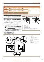
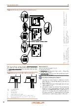
Gas change procedure (Figure 5.3
1.
Cut off electric power and gas supply.
2.
Remove front and left panel.
3.
Remove the wires from the gas valve.
4.
Remove the ring nut (H) from the threaded gas nozzle (C).
5.
Remove the gas nozzle (C) from the gas valve (A) by remov-
ing the 4 screws (G) from the valve flange (use 9/64" hex key
wrench). Put the o-ring (D) in a safe place, to be re-used with
the new nozzle.
6.
Attach the new gas nozzle to the gas valve using the 4
screws to secure valve flange: be sure to put the o-ring in
the proper site.
7.
Tighten the ring nut and re-attach wires to the valve.
8.
Restore the gas and electrical supply.
9.
Adjust the gas pressure for the gas to be used following the
instructions reported in Paragraph 5.4
10.
Replace the sticker indicating the type of gas for which the
unit is preset with the new one, which indicates the type ac-
tually being used.
Figure 5.2
Gas valve
1
gas valve
1
Summary of Contents for GAHP-AR
Page 43: ......

