System design
20
3
3
SYSTEM DESIGN
3.1
WARNINGS
General warnings
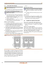
Read the warnings in Chapter III.1
p. 4, providing im-
portant information on regulations and on safety.
Compliance with installation standards
The installation of the appliance must conform to the
requirements of the authority having jurisdiction or, in
the absence of such requirements, to the latest edition
of the
National Fuel Gas Code, ANSI Z223.1
. If the unit
is installed in Canada, the installation must conform to
the
Canadian Gas Association Standard CAN1 B149.1
and .2
.
Installation must comply with applicable regulations in
force, based on the installation Country and site, in mat-
ters of safety, design, implementation and maintenance
of:
heating systems
cooling systems
gas systems
flue gas exhaust
flue gas condensate discharge
Installation must also comply with the manufacturer's
provisions.
The manufacturer cannot be held responsible for any
damages to persons, animals or goods due to improper,
erroneous or irrational installation of these appliances.
3.2
HYDRAULIC SYSTEM
Primary and secondary circuit
▶
In many cases it is advisable to divide the hydraulic system
into two parts, primary and secondary circuit, uncoupled by
a hydraulic separator, or possibly by a tank that also acts as
inertial tank/buffer.
Water flow rate
The GAHP-AR unit works with constant, water flow and ON/OFF
operative mode.
System and components must be designed and installed con-
sistently. The water lines should also be sized so the maximum
velocity of the water/monoethylene glycol solution in the lines
does not exceed 6 feet per second to avoid excessive noise.
There must be correct water flow when the unit is operating and
during the shutdown cycle (600 seconds, between turning the
burner off and complete shutdown of the appliance).
Minimum water content
High thermal inertia is conducive to efficient appliance opera-
tion. Very short ON/OFF cycles are to be avoided.
▶
For each GA unit provide a minimum water content in the
installation of at least 20 gallons.
Buffer tank
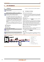
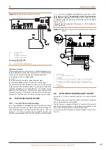
If using a buffer tank, it can be with 2 or 4 hydraulic connections,
as shown in the following two diagrams (Figure 3.1
3.2
Figure 3.1
2-pipe tank diagram
1
Anti-vibration connection
2
Pressure gauge
3
Inlet flow control device
4
Water filter
5
Shut-off valves
6
Water pump (primary circuit)
7
Safety valve
8
Expansion tank
9
Hydraulic separator
10 Water pump (secondary circuit)
11 2-connection inertial buffer tank
Summary of Contents for GAHP-AR
Page 43: ......


