Electrical installer
28
4
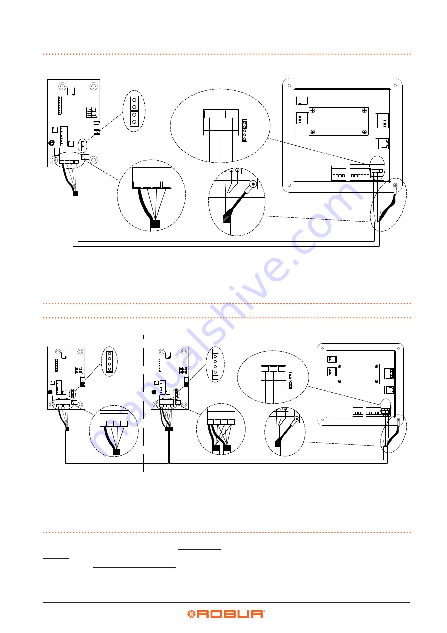
Figure 4.6
CAN bus connection for systems with one unit
DDC Direct Digital Controller
SCH CAN-NDG board
J11 CAN bus jumper on CAN-NDG board
J21 CAN bus jumper on DDC panel
GND Common data
0
Common data
H Data signal HIGH
L
Data signal LOW
A Terminal node connection - (3 wires; J11
and J21 = "closed")
B
CAN bus cable shield
C
Insulating tape to protect the shield of the
CAN bus cable
D Eyelet terminal and fixing screw
P8 CAN port/connector
JUMPER
J11
H
2
1 3 4
1
4
3
2
5 6
L
H
GND
JUMPER J21
A
GND
L
0
L
H
SHIELD
E-SL
T088 CAN-NDG
E-SL
T088 CAN-NDG
J11
A
DDC
SCH
B
C
D
P8
0 L H
SHIELD
A
Figure 4.7
CAN bus connection for systems with multiple single units
DDC Direct Digital Controller
SCH CAN-NDG board
J11 CAN bus jumper on CAN-NDG board
J21 CAN bus jumper on DDC panel
GND Common data
0
Common data
H Data signal HIGH
L
Data signal LOW
A Terminal node connection - (3 wires; J11
and J21 = "closed")
B
Intermediate node connection - (6 wires;
J11 and J21 jumpers = "open")
C
CAN bus cable shield
D Insulating tape to protect the shield of
the CAN bus cable
E
Eyelet terminal and fixing screw
P8 CAN port/connector
JUMPER J11
H
2
1 3 4
1
4
3
2
5 6
L
H
GND
JUMPER J21
A
GND
L
0
L
H
SHIELD
E-SL
T088 CAN-NDG
E-SL
T088 CAN-NDG
J11
A
DDC
SCH
C
D
E
P8
JUMPER J11
0
L
H
SHIELD
E-SL
T088 CAN-NDG
E-SL
T088 CAN-NDG
J11
B
SCH
0 L H
SHIELD
0 L H
SHIELD
A
B
Place the CLOSED J21 Jumpers (Detail A) if the node is
terminal (one connected CAN bus cable section only), or
OPEN (Detail B) if the node is intermediate (two connect-
ed CAN bus cable sections).


