background image


3710308617_DICHIARAZIONE CE_GB 

eC DeCLARATiOn Of COnfORMiTy 

(Annex IIA DIr. 2006/42/EC)


Robopac s.p.A. 

via fabrizio da Montebello, 81 - 47892 
gualdicciolo republic of San Marino 

DeCLARes ThAT The MAChine 


is in COnfORMiTy WiTh DiReCTiVes 

European Parliament and Council Directive 2006/42/EC dated May 17, 2006 
European Parliament and Council Directive 2004/108/EC dated December 15, 2004 
European Parliament and Council Directive 2006/95/EC dated December 12, 2006 

Reference to harmonised standards and relevant annexes, in applicable points: 

EN ISo 12100:2010, EN 60204-1:2006/A1:2009, EN 415-5:2010, EN 415-6:2013, EN 415-10:2014. 


The inDiViDuAL AuThORiseD TO DRAfT The TeChniCAL BOOkLeT is 

 
Mr. Pierangelo Laghi, R&D Manager


Via fabrizio da Montebello, 81 - 47892 Gualdicciolo (RsM) 

 Republic of san Marino 


Document date and place                                                                                          signature


san Marino,                                                                                                          

 
______________________________________________________________________________________ 

Summary of Contents for Rotoplat DW 108-508

Page 1: ...W C 108 508 serial n GB USE AND MAINTENANCE MANUAL Translation of the original instructions MACHINE WITH ROTATING PLATFORM FOR WINDING PLASTIC STRETCH FILMS Instructions manual code 3710308590 English Edition 1 1114 ...

Page 2: ......

Page 3: ...ated December 15 2004 European Parliament and Council Directive 2006 95 EC dated December 12 2006 Reference to harmonised standards and relevant annexes in applicable points EN ISo 12100 2010 EN 60204 1 2006 A1 2009 EN 415 5 2010 EN 415 6 2013 EN 415 10 2014 The inDiViDuAL AuThORiseD TO DRAfT The TeChniCAL BOOkLeT is Mr Pierangelo Laghi R D Manager Via fabrizio da Montebello 81 47892 Gualdicciolo ...

Page 4: ......

Page 5: ...30 4 INFORMATION ON HANDLING AND INSTALLATION OPERATIONS 4 1 RECOMMENDATIONS FOR HANDLING AND LOADING 31 4 2 PACKAGING AND UNPACKING 31 4 3 TRANSPORT AND HANDLING 32 4 4 INSTALLATION OF DISMOUNTED PARTS 32 4 5 FASTENING THE MACHINE 35 4 6 RECOMMENDATIONS FOR CONNECTIONS 35 4 7 PNEUMATIC CONNECTIONS 36 4 8 ELECTRICAL CONNECTION 36 5 INFORMATION ON ADJUSTMENTS 5 1 RECOMMENDATIONS FOR ADJUSTMENTS 37 ...

Page 6: ...BLE 73 7 3 LUBRICATION POINT DIAGRAM 74 7 4 LUBRICANTS TABLE 75 7 5 CONDENSATE DISCHARGE 76 7 6 CLEANING THE AIR FILTER 76 8 TROUBLESHOOTING 8 1 ALARM MESSAGES 77 9 SPARE PARTS REPLACEMENT INFORMATION 9 1 RECOMMENDATIONS FOR REPLACING PARTS 79 9 2 REPLACING ROTATING TABLE WHEELS 80 9 3 LIST OF THE RECOMMENDED SPARE PARTS 81 9 4 MACHINE DISPOSAL AND SCRAPING 81 10 ENCLOSED DOCUMENTATION 10 1 WARRAN...

Page 7: ...well known and easy to access place available for reference any time the need should arise Refer to the table of contents and the analytical index in order to easily identify the subjects of interest Some information may not correspond completely to the actual configuration of the machine delivered Any additional information does not affect the readability of the text and the safety level The manu...

Page 8: ...ectly on the machine It contains references and indispensable operating safety indications A Machine model B Machine s serial number C Year of manufacture D Power supply voltage E Power supply frequency F Power supply phases G Electrical power consumption H Total installed power L Air consumption M Max air supply pressure N Machine weight P Manufacturer s name ...

Page 9: ... use and ordinary maintenance of the machine Maintenance technician A person authorised and chosen among those who have the requirements skills and information necessary to perform ordinary and extraordinary machine maintenance He is expected therefore to possess precise information and skills with particular expertise in the field of intervention Format Change series of operations to carry out on...

Page 10: ...ted address for all your needs ROBOPAC SPA VIA FABRIZIO DA MONTEBELLO 81 47892ACQUAVIVAGUALDICCIOLO REPUBBLICAS MARINO RSM Phone 0549 international 378 910511 Fax 0549 908549 905946 http www aetnagroup com 1 5 ATTACHED DOCUMENTATION The machine is provided with the documentation listed below in the absence of a different trade agreement Warranty conditions Pneumatic circuit diagram Wiring diagram ...

Page 11: ... the good manufacturing regulations and the standards in force The machine has been designed to be constructed and equipped with devices that ensure intrinsic safety Tampering with the safety devices and the removal of the same may create risks even severe for the operators The personnel authorised to carry out any operation with the machine must have acknowledged experience in the specific field ...

Page 12: ...reas that are dangerous and hard to access Install the machine according to the minimum perimeter indicated by the manufacturer and the surrounding activities Should the machine interface directly indirectly with other machines or production lines draw up the installation design of the machine The design must include all the operating conditions in order to comply with the standards in force on sa...

Page 13: ...ery with the safety devices not properly installed and efficient ALWAYS wear the individual safety devices indicated in the Instructions for use and provided by the standards in force regarding the safety at workplace ALWAYS keep the surrounding areas in suitable conditions and free of obstacles in order to minimise the risks especially near the control station The machine must be used by one oper...

Page 14: ...ucts that are loose that have an irregular shape or that are not suitably collected to prevent inadequate palletisation Do not use the machine to wrap and stabilise living beings animals and humans DO NOT use the machine with wrapping material different from that provided by the manufacturer Do not use the machine as a lifting device or as a rest surface for work activities for example a workbench...

Page 15: ...ining make sure the operator has understood the contents in the use manual especially the information regarding safety The operator must possess the required training and meet the suitable conditions for carrying out the activities in safety conditions The employer must inform the operator on the INCORRECT USES predictable and on the persistent Residual risks The operator must be capable of readin...

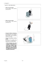
Page 16: ...rs The residual risks are all the risks that persists although all safety solutions have been applied and integrated during machine design The list specifies the residual risks specific for this type of machine Dangerofcollisionandslipping Do not get onto machine partsduring its operation Dangerofcollisionandslipping do not come near machineparts during its operation Upper limb cutting hazard Do n...

Page 17: ...climb onto machine parts i e the turntable with the lifting device while the machine is running Danger of projecting or falling objects Do not use the machine at a speed that is not appropriate for the product you need to wrap If the packages you need to wrap contain unstable or hazardous elements you must adopt suitable safety precautions i e perimeter guards to prevent the risk of harming the ph...

Page 18: ...cturer DO NOT use products that contain corrosive toxic and inflammable substances Wear the Individual Protection Devices provided by the laws on workplace safety and indicated in the Instructions for use and or affixed to the machine Replace the components ONLY with ORIGINAL PARE PARTS or with SIMILAR design and functional features The use of similar but non original spare parts may lead to impro...

Page 19: ...the plates are clearly readable and if necessary replace them with new ones that shall be positioned in the same places as previously A Electrical hazard sign Do not access this area risk of electrical shock or electrocution B Information sign Indicates the points for lifting with a hook device C Information sign indicatesthe lifting points with a fork device D Information sign Indicates the direc...

Page 20: ...sh Chapter 2 SAFETY INFORMATION 2 8 SURROUNDING AREAS The illustration depicts the perimeter work areas of the machine A Operator s working area B Pallet loading unloading area C Sorrounding area Min 800 Min 800 Min 800 Min 800 Min 1500 Min 1500 Min 1500 Min 1500 ...

Page 21: ...let and a reel carriage that unwinds and stretches the film It is equipped with a series of safety devices designed to avoid anyharm befalling the operator or other persons who come into contactwith the machine in any way The machine is produced in a range ofdifferent models in order to suit market requirements The loads are wrapped using reels of stretchable film which can be readily found on sal...

Page 22: ...esshow the data and the main specifications Locking clamps Rotating table Pressure platen Carriage drive Slide guide mast Control panel Table drive Locking clamps Rotating table Carrier Pressure platen Carriage drive Slide guide mast Control panel Table drive Locking clamps Base Pedal Reel carriage Locking half flange optional Unlocking foot switch Base Pedal Reel carriage ...

Page 23: ...8 Rotoplat with film carriage type PDS Rotoplat DW C 508 Table 3 2 Roll holder carriage specifications Type of reel holdingcarriage General Requirements FRD FRD reel carriage with clutched roller mechanical brake and manual coating draw adjustment PDS PDS typespoolcarriage withdrivenpre stretch rollers and electronic film tensioning Pre stretching is adjustable from control panel 0 25 ...

Page 24: ...ready to start a new one 3 3 DESCRIPTION OF THE OPERATION CYCLE ROTOPLAT DW C 108 508 Phase 1 The operator positions the product having it slide onto the conveyor and using the pedal control has the presser come down to lock the top part With the pedal control beside the carrier long lever the operator locksthelowerpartoftheproduct Phase 2 Once the cycle has started the turntable starts turning wh...

Page 25: ...cked to prevent unauthorisedpersonnel from startingthe machine during adjustmentsand maintenance D Acoustic signal signals the start of the wrapping cycle E Switch for Pluriball carriage stops the descent in presence of obstacles below the reel carriage G Emergency button the machine stops immediately when this button is pressed in emergency situations To reset rotate the button in the direction i...

Page 26: ...or enables the in phase stop of the rotary table G Load cell sensor it detects the tension of the film and enables thespeed variation of the pre stretching rollers 3 5 DESCRIPTION OF THE ELECTRICAL DEVICES The figure shows the positioning of the devices on board of the machine A Gear motor activates table rotation H Electric motor it drives the pre stretch rollers M Trolley lifting sensor it defin...

Page 27: ...ESONREQUEST To enhance the performance and to increase the versatility of the machine the manufacturer furnishes the accessories listed below Mechanicalpressureplaten A electrically controlled device to stabilise the load it is not necessary to adjust the height depending on the dimensions of the product to be wrapped Stabiliser plate B device for stabilising the palletised loads ...

Page 28: ...rs or sides using Pluriball orsimilar reels It is equipped with quick load film and a safety device to stop the carriage Rotating table ø1800 towrap larger than standardloads Sliding guide mast 2800 3100 mm to wrap taller than standard loads Locking half flange Locking device on the worktable of the product to be wrapped Theproductlocksontheworktable by pushing one of the two half flanges E with a...

Page 29: ...ify the dimensional characteristics and technicaldata of the machine Table 3 3 Door and window dimensions B mm C mm D mm E mm F mm L mm W mm H mm 2780 H 2100 3180 H 2500 3480 H 2800 1650 2755 1790 2313 320 1650 40 380 2100 B 2780 2500 B 3180 2800 B 3480 1800 2835 1865 2313 320 1800 40 380 Door and window dimensions Palletised load dimensions ...

Page 30: ... specifications Description Units of measurement Value Supply voltage V 220 240 1Ph 220 240 3Ph 380 415 3Ph N Electrical supply frequency Hz 50 60 Installed power kW 1 5 Rotoplat DW 108 1 9 Rotoplat DW 508 Table rotational speed C 1650 rpm 5 12 C 1800 5 11 Carriage up down speed m min 1 5 5 5 Total weight kg 380 640 Ambient operating temperature C 0 40 Table 3 6 Presser technical specifications De...

Page 31: ...cify the dimensional characteristics and technicaldata of the machine Table 3 7 Door and window dimensions B mm C mm D mm E mm F mm L mm W mm H mm 2780 H 2000 3180 H 2400 3480 H 2700 1650 2755 1790 2313 320 1650 40 210 2000 B 2780 2400 B 3180 2700 B 3480 1800 2835 1865 2313 320 1800 40 210 Door and window dimensions Palletised load dimensions ...

Page 32: ...ecifications Description Units of measurement Value Supply voltage V 220 240 1Ph 220 240 3Ph 380 415 3Ph N Electrical supply frequency Hz 50 60 Installed power kW 1 5 Rotoplat DW C 108 1 9 Rotoplat DW C 508 Table rotational speed C 1650 rpm 5 12 C 1800 5 11 Carriage up down speed m min 1 5 5 5 Total weight kg 380 640 Ambient operating temperature C 0 40 Table 3 10 Presser technical specifications ...

Page 33: ...Coil technical specifications Description Units of measurement Value Film spool dimensions A Maximum external diameter D mm 300 Reel height H mm 500 Film thickness μm 17 35 Internal diameter d mm 76 Max weight kg 20 Bubble film spool dimensions B Maximum external diameter D mm 1000 Reel height H mm 500 Internal diameter d mm 76 Max weight kg 12 ...

Page 34: ...or personnel Therefore we suggest the following prerequisites Suitable room temperature See Technical data ROTOPLAT DW 108 508 Technical data ROTOPLAT DW C 108 508 A suitably aired place so that when the machine is working the degree of humidity is not unpleasantly high low from the point of view of the operator A sufficient lighting in order that a pleasant relaxing working environment is created...

Page 35: ...e RESIDUAL RISKS 4 2 PACKAGING AND UNPACKING The packing is realised keeping the overall dimensions low also in consideration of the transport chosen To facilitate transport shipping can be performed with some components disassembled and appropriately protected and packaged Some parts especially electric equipment are protected with anti moisture nylon covers The cases are marked with all necessar...

Page 36: ...sudden shifting Important For further transportation recreate the initial packaging conditions for transport and handling 4 4 INSTALLATION OF DISMOUNTED PARTS Following are the steps to be taken to install dismantled parts Electrical box assembly Proceed as indicated 1 Cut the band A that holds the electrical wires together 2 Remove the blocking rods B 3 Insert the electrical wires C in the slide ...

Page 37: ... the hinge 2 Insert the screws L in the hinge without tightening them Only forsliding shaft with height 2800 3100 mm 3 Secure the hook of the lifting equipment to the bracket M of the sliding mast and tension it Only forsliding shaft with height 2200 2400 mm 4 Lift the sliding mast H 5 Secure the sliding mast to the machine body with the screws N 6 Tighten the hinge screws L Carrier assembly 1 Mou...

Page 38: ...ant If the pressure platen is delivered with the machine the pneumatic connections have already been performed by the manufacturer Pluriball kit assembly optional 1 Remove the reel carriage U 2 Assemble the frame V on thesliding guide mast 3 Assemble the rollers W on theframe V using the screws X 4 Assemble the reel carriage on the frame V Assembly of the mechanical pressure platen optional 1 Fast...

Page 39: ...e machine are fundamental operations for ensuring the stability and correct functioning of the machine Important If necessary insert metal plates A between the screws and the floor 4 6 RECOMMENDATIONS FOR CONNECTIONS Important Connections should be performed following the manufacturer s indications in the enclosed diagrams Personnel authorised to perform this operation must possess technical skill...

Page 40: ...of at least 6 bar and turn knob C to compensate any pressure differences Repeat this operation with the machine running 4 8 ELECTRICAL CONNECTION Proceed as follows for electrical connections 1 Check that the mains voltage V and frequency hertz correspond to those of the machine see identification plate and wiring diagram 2 Turn the mains switch to 0 OFF 3 Connect the power cord to the outlet A as...

Page 41: ...any residual energy is still present Provide suitable safety conditions in compliance with the regulations on workplace safety to prevent and minimise the risks Pay attention to the SAFETY WARNINGS do not use the machine for UNSPECIFIED PURPOSES and assess the possible RESIDUAL RISKS Chapter 5 INFORMATION ON ADJUSTMENTS 5 2 ADJUSTING FILM STRETCH FRD type reel carriages 1 Use lever A to lock and u...

Page 42: ...transmission cover A 3 Loosen the belt C through the tensioner B 4 Remove the belt from the pulley D 5 Loosen the screws E 6 Remove the disk F including the motor and bearings 7 Remove the stopping ring G 8 Remove the pulley D 9 Remove the stopping ring H 10 Remove the gear L 11 Remove the stopping ring M 12 Remove the gear N 13 Loosen the screws and remove the small plate P from the gear N 14 Sel...

Page 43: ...ew driving ratio 16 Assembly the gear of the new driving ratio 17 Position the gear with the side of the small plate coupled to the friction 18 Assembly the stopping ring 19 Assembly the gear of the new driving ratio 20 Assembly the stopping ring 21 Assembly the pulley 22 Assembly the stopping ring Important During re assembly remember to pay attention to the proper insertion of the coupling tabs ...

Page 44: ... to top end stroke 2 Switch the machine off 3 Loosen the screws A and tilt the stake resting it on the plate 4 Remove the guard B 5 Loosen the nuts C 6 Tighten the screw D M8x50 UNI 5739 element not supplied with a torque wrench element not supplied up to the torque 3 Nm 7 Re tighten the nuts C up to the surface of the chain tightening pulley E 8 Undo screw D 9 Refit the guard B 10 Re position the...

Page 45: ...ALL REEL BRAKE ADJUSTMENT To create correct film tensioning use the hand wheel L that adjusts reel braking 5 4 TABLE ROTATION CHAIN ADJUSTMENT Proceed as indicated 1 Remove the cover guard A 2 Loosen the fastening screws B of the gear box 3 Tighten the screw C with a torque wrench element not supplied up to the torque 5 Nm 4 Tighten the reducer fastening screws B when finished 5 Refit guard A ...

Page 46: ...roduct proceed as follows 1 Loosen the handles A 2 Shift the supports B into the desired position 3 Tighten the handles A To adjust based on the thickness of the product proceed as follows 1 Loosen the handles C 2 Shift the grippers D into the desired position 3 Tighten the handles C Rotating worktable grippers Rotoplat DW C The grippers can be adjusted based on the thickness of the product to be ...

Page 47: ...cated 1 Loosen the handles G 2 Shift the grippers H into the desired position 3 Tighten the handles G Importante Adjust the positions of the grippers so that the product to be wrapped is aligned as much as possible with the rotating worktable 5 7 CARRIER HEIGHT ADJUSTMENT Proceed as indicated 1 Loosen the screws A 2 Manually shift the frame B so that the carrier is aligned with the inlet and outle...

Page 48: ...INFORMATION ON ADJUSTMENTS 5 8 CAM ADJUSTMENT FOR THE HEIGHT OF THE COATING WRAPPING Adjust the position of the control cam of the microswitch that fixes the height of the coating wrapping 1 Loosen the hand wheel A 2 Move the cam B 3 Fix the position by tightening the handwheel A ...

Page 49: ...r further details consult the paragraph Description of safety devices B User interface it is used to set or modify the operating parameters of the machine For further details consult the paragraph Description of the user interface C Start cycle push button it is used to start the automatic wrapping cycle D Stop cycle button it is used to stop the automatic wrapping cycle When pressed during the lo...

Page 50: ...of the push button on the right of the various recipes of the Recipes screenshot The page displays the wrapping parameters currently in use and gives access the other pages 2 Manual handling screenshot The screenshot shows he controls to activate the handling of functions in manual mode 3 3 1 Recipes screenshot The screenshot displays the controls to activate the desired recipe 4 Wrapping cycle sc...

Page 51: ... 47 3 3 1 2 1 5 4 6 7 10 9 8 English 47 Chapter 6 ABOUT THE USE ...

Page 52: ... 48 3 2 1 1 5 6 7 10 9 8 3 3 1 English Chapter 6 ABOUT THE USE ...

Page 53: ...alphanumeric keypad N Name Function description A Displaying area The area displays the numeric and alphanumeric characters B Push button The activation of the control closes the screenshot and the values entered are not stored C Push button The activation of the control cancels the character selected D Push buttons The activation of the control cancels a character at a time starting from the last...

Page 54: ...rameter programmed The window is displayed each time an area that can be changed or programmed is pressed A Area displays the icon corresponding to the parameter to be programmed The illustration shows a typical example of window and the table shows the description of icons Table 6 3 Description of icons Icon Function description 1 Lower wrapping 2 Reinforcement wrapping 3 Upper wrapping 4 Coating...

Page 55: ...ementwrapping in the middle area of the pallet The number displayed indicates the value programmed G Push button used to program the quantity of wrapping at the base of the pallet The number displayed indicates the value programmed H Push button used to program the stretch value of the coating The number displayed indicates the value programmed L Push button used to program the pre stretch value o...

Page 56: ...ontains only the keys that can be activated The list shows the description of the elements push buttons icons Etc displayed in the area Push button used to display the Recipes screenshot The number displayed indicates the activated recipe Area displays the name of the activated recipe Push button impulse used to bring back the trolley to the down limit stop With the trolley at the down limit stop ...

Page 57: ...se E Push button JOG used to activate the lifting of the presser arm F Push button JOG used to activate the lowering of the presser arm G Push button JOG used to activate the return of the trolley and the timing of the worktable H Push button used to display the Home screenshot 6 5 1 MANUAL REINFORCEMENT FUNCTION Important It is not possible to carry out this function from layer recipes During the...

Page 58: ... DX push buttons used to activate the layer cycle E Push button used to copy the data of a recipe on another one F Push button used to display the screen of the successive recipes G Push button used to display the screen of the previous recipes Keep the key A pressed the trolley stops carrying out reinforcement turns until the key is released Repeatedly press the A key the trolley carries out as m...

Page 59: ...ed Icon D2 used to select the programmed stopping of the spool carriage lifting phase depending on the height of the pallet By activating this button altimeter another button opens next to the E button which allows you to set the height of the pallet With this function activated if you wish to delay the wrapping you must set a height that is greater than that of the product to be wrapped E Button ...

Page 60: ...ight and the number of reinforcement wrapping The push buttons are only visible if the function was enabled through the button H M Push button used to enable and disable the programming of the cycle with the presser Optional N Push button used to access the page of special cycles F1 F2 ...

Page 61: ...ODUCTION COUNTERS PALLETS SCREENSHOT The screenshot displays the controls to check the quantity of pallets made partial and total A Area displays the counter total of wrapping cycles carried out by the machine B Area displaysthecounter partial of wrapping cycles carried out by the machine C Push button used to reset the counter B The function is active only if the system is accessed as machine res...

Page 62: ...stem is accessed as machine responsible see the password insertion user login screenshot D Push button used to display the screenshot showing the software version E Push button used to select the language F Push button used to display the screenshot for adjusting the date ad hour A Push button used to display the upper level screenshot B Area displays the characters entered C Numeric keypad D Push...

Page 63: ...nce icon Icon A1 used to select the machine responsible user Icon A2 used to select the assistance service user Icon A3 used to select the software administrator user B Area displays the characters entered C Numeric keypad D Push button used to confirm the password entered login To prevent another type of user from accessing the protected functions at the end of the operationsuseoneofthefollowing ...

Page 64: ...utton used to display the state of various components of the electric panel B Push button used to display the state of MODBUS C Button it is used to display the offset of the loading cell D Push button used to display the state of motors E Push button used to update the software F Push button used to display the general configuration parameters of the machine G Push button used to display the alar...

Page 65: ...recipe to access the Home 1 1 screenshot 4 If required press the key E to copy the data of a recipe on another one 5 Select the concerned recipe 6 Program the name of the recipe 7 Press the button B to display the Home 1 screenshot 8 Press the push button C to display the wrapping cycle 4 screenshot 9 Program the parameters of the recipe The area D displays the preview of the pallet wrapping cycle...

Page 66: ...g 4 Perform the cycle start operations see 6 19 Starting and stopping the cycle 5 Turn the main switch A to 0 OFF to turn the machine off 6 16 CYCLE PARAMETER SETTING Proceed as indicated Switch the machine on see 6 15 Switching the machine on and off Choose the recipe number Press the button relative to the parameter to be modified to view the current value The LED on button switches on Press the...

Page 67: ...ving accomplished the preset number of rounds at the bottom and top of the pallet If you press the START button again a second wrapping cycle is carried out starting from the top and ending at the base of the pallet see6 7 Wrappingcycle screenshot Double wrapping cycle To select the double cycle press key C2 and check that corresponding led lights up The reel carriage moves off from the bottom of ...

Page 68: ... machine is fitted with a top pressure platen this lifts from the load by about 200 mm At this point the operator after having positioned the covering sheet on the top of the pallet reactivates the cycle by pressing the Start button the presser descends once more The carriage rises again until it reaches the top of the pallet performs the set number of upper wrappings of the pallet then descends o...

Page 69: ...roceed in the following way Whenever the type of pallet requires the use of the pneumatic presser proceed as follows 4 Undo screw E 5 Dismantle the blocking device F Rotoplat DW 1 Loosen the screws A 2 Dismantletheblockingdevice B 3 Press the button C to deactivate the presser Rotoplat DW C 1 Dismantle the carrier D 2 Press the button C to deactivate the presser 3 Setthe Photocelldelay parameter t...

Page 70: ... STARTING AND STOPPING THE CYCLE Proceed as indicated 1 Place the load on turntable and set aside the loading device 2 Block the edge of the film in the clasping disk on the rotating table 3 Press the Cycle start push button A The machine performs a cycle and stops automatically 4 Proceed to film cutting 5 Remove the load and place another one on the table to start a new cycle Important To pause t...

Page 71: ...bles to identify the minimum height of the pallet to be wrapped depending on the version of the presser assembly installed on the machine Door and window dimensions 1 Loosen the screw A 2 Adjust the height of the pneumatic cylinder B on the guide C accordingtothesizeoftheproduct to be wrapped 3 Tighten the screw A Table 6 4 Height of presser Rod pneumatic cylinder Presser assembly version Slide gu...

Page 72: ... Adjust the height of the pneumatic cylinder B on the guide C accordingtothesizeoftheproduct to be wrapped 3 Tighten the screw A Table 6 5 Height of presser Rod pneumatic cylinder Presser assembly version Slide guide mast Arm in Normal position H mm H1 mm H2 mm Rod pneumatic cylinder 2350 2200 1400 2550 2400 1400 2950 2800 1400 3250 3100 1400 ...

Page 73: ...embly version Slide guide mast Rotoplat DW 108 508 Rotoplat DW C 108 508 H mm H1 mm H2 mm H3 mm H4 mm Mechanical presser 2760 2100 550 2000 450 3160 2500 550 2400 450 3460 2800 550 2700 450 Mechanical presser Palletised load dimensions This presser does not need to be adjusted for wrapping heights greater than 750 mm Table 6 7 Height of presser Presser assembly version Slide guide mast Arm in Norm...

Page 74: ...ween the double cone surfaces Important Unwind the film according to the procedure shown on the label applied on the roll holder carriage plate 3 Pull the cord outwards The film will automatically drop on the roller and cover it all along its height 4 Block the edge of the film in the clasping disk A on the rotating table On FRD carriages to permit the insertion of the coating between the rollers ...

Page 75: ...E 6 22 PLURIBALL REEL LOADING Proceed as indicated 1 Insert film reel in the proper housing on the reel carriage 2 Unwrap the film and place it between the rollers according to the diagram depicted on the plate 3 Adjust reel brake see 5 5 4 Block the edge of the film in the clasping disk A on the rotating table ...

Page 76: ...with all the safety devices enabled and wear the DPI provided Mark the intervention area and prevent access to the devices that if activated may cause unexpected hazards and jeopardize the safety level DO NOT carry out any intervention that is not described in the manual but contact an Assistance Service authorised by the manufacturer DO NOT damp in the environment materials pollutant liquids and ...

Page 77: ...oint diagram Tensioning check Adjust See Reel carriage lifting chain adjustment Table rotation chain Greasing See Lubrication point diagram Tensioning check Adjust See Table rotation chain adjustment Reduction gears and gearmotors Lubricant level check 1 Top up with a lubricant of the same kind if necessary See lubricants table Toothed wheels of the carriage drawing gears Greasing See Lubrication ...

Page 78: ...NFORMATION 7 3 LUBRICATION POINT DIAGRAM The following diagram shows the main components and the frequency of the lubrication interventions Symbol and Description Smear with grease Check lubricant level Do not top up and or replace the lubricant in reduction gears and gearmotors lubricated for life ...

Page 79: ...P 320 SHELL ENERGOL GR XP 320 BP 32 C a 50 C 460 CST a 40 C Worm gear motor MELLANA OIL 460 IP SPARTAN EP 460 ESSO BLASIA 460 AGIP MOBILGEAR 634 MOBIL OMALA EP 460 SHELL ENERGOL GR XP 460 BP Grease TELESIA COMPOUND B IP Gear and worm gear motor STRUCTOVIS P LIQUID KLUBER TOTALCARTER SYOO TOTAL Synthetic oil TELESIA OIL IP SYNTHESO D 220 EP KLUBER BLASIA S 220 AGIP Lithium grease ALVANIA R2 SHELL B...

Page 80: ...d 1 Unscrew the container B with the wrench 2 Detach the filter and clean with compressed air and wash if necessary with petrol or trichloroethylene 3 Reassemble the filter and tighten the container B Proceed as indicated 1 Close the tap A and control the level of condensation in the container B 2 Unscrew if necessary the valve C to empty condensation 3 Push the valve C up until all condensation i...

Page 81: ... has been detected on the platform loading unloading ramp Remove the obstacle and press the Reset button E04 Guard alarm Intervention of safety barriers or door open Remove the obstacle and press the Reset button E30 Fault Inverter overload 1 Worktable 2 Trolley 3 Pull 4 Drawing 5 Pressure platen POWER DRIVER LOW POWER DRIVER HIGH OVER VOLTAGE MAX VOLTAGE UNDER VOLTAGE HW POWER CURRENT OVER HEAT P...

Page 82: ...ed Use the specific lever to lock the roller conveyor The roller conveyor is not synchronised Press the Start cycle button together with the key yellow Worktable rotation speed to being the roller conveyor to the pallet loading unloading position E83 Modbus Alarm Electronic fault Contact the Servicing Dept ...

Page 83: ... not described in the manual but contact an Assistance Service authorised by the manufacturer DO NOT damp in the environment materials pollutant liquids and the residues created during the interventions but dispose them according to the standards in force Replace the components ONLY with ORIGINAL PARE PARTS or with SIMILAR design and functional features The use of similar but non original spare pa...

Page 84: ...nglish Chapter 9 SPARE PARTS REPLACEMENT INFORMATION 9 2 REPLACING ROTATING TABLE WHEELS Proceed as indicated 1 Loosen the screws A 2 Assemble the eyebolts B on the rotating table C 3 Lift the table and place it on the floor 4 Replace the wheels D 5 Position the table on the base and fasten it with the screws ...

Page 85: ...t of service Disconnect the supplies to the machine electrical pneumatic etc so that it cannot be restarted and position it in a place not easy to access Empty in ad adequate way the systems containing damaging substances and do it in accordance with the current laws in force at workplaces and those regulating environmental protection Machine scrapping Scrapping must be entrusted to authorized cen...

Page 86: ...duction or injuries to persons or damage to things caused by malfunctions or forced suspension in using the machine covered by the warranty The warranty does not cover damage caused by transport damage due to incorrect installation improper use of the machine or negligence tampering or repairs by unauthorised personnel lack of maintenance parts subject to normal wear and tear For purchased compone...

Page 87: ...OSED DOCUMENTATION 10 2 PRESSURE PLATEN PNEUMATIC DIAGRAM Pneumatic circuit diagram Rod pneumatic cylinder Key A Filter regulator unit B Solenoid valve C Flow regulator D Silencer E Discharge solenoid valve F Presser drive pneumatic cylinder ...

Page 88: ... 84 English Chapter 10 ENCLOSED DOCUMENTATION Page deliberately empty ...

Reviews: