JZY-B920
16
703
403
×
(fillet: 4-R15)
2
780
×
450
138
×
Product Size(mm)
Gas Style
Rated Pressure
Heating Load(kW)
Gas Connector
Item Name
Item No.
Net Weight(kg)
Gas Burner
Air in flow
Panel
lgnition Method
Installation Size(mm)
Gas Hob
See the label
φ
9.5mm special gas rubber gasket (G1/2 inch special metal gasket)
Full
Tempered Glass
Note
:
See the label
See the label
Pulse
Performance Parameters
Installation Instruction
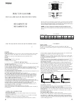
1.The distance between an installed stove and its surroundings shall be no less than 15 cm and a clear
height no less than 100 cm shall be reserved above the stove. If an extractor hood is to be installed, the
c l e a r h e i g h t s h a l l b e s e t a s p e r t h e i n s t a l l a t i o n r e q u i r e m e n t s o f t h e e x t r a c t o r h o o d .
2.The cupboard where an embedded gas stove is going to be installed shall have an atmosphere-
2
connected opening that satisfies ventilation requirements (with an area no less than 100 cm ), so as to
avoid explosion caused by deposited leaked gas.
3.If special gas hose is adopted, one end of the hose shall be connected with the valve of gas source and
the other end shall be connected with the gas inlet of the gas stove (Note: Please remove the protective cap
on the joint). The hose ends shall cover the red marks and secured by the clamps provided randomly. In the
meantime, leakage detection shall be carried out to make sure there is no leakage. After that, the product
can be used.
4.An opening shall be made as per the size of the opening template. The stove shall be embedded evenly in
the opening.
5.If
G1/2
' interface is adopted, the joint of the
φ9.5 hose must be screwed off, a rubber washer shall be
applied on the interface and the nut shall be screwed down. After
that, leakage detection shall be carried
out before using.
6.High quality qualified relief valve must be used by LPG stove.
7.When placing a copper cap, the locating rod must be inserted in the locating hole of the aluminum seat, so
that the cap can be put in place without any movement.
5
Gas Hob
Note
:
the
Indian
market
uses
specified
rubber
hose
connector
1.All the parameters in table are provided for reference only and subject to the specific data on the
nameplate of stove.
2.The opening size of embedded stove shall subject to the size of the opening template in carton.
3.The Company reserves the rights of modifying products' designs and specifications.
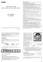
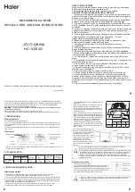
Switch
Pan
Stand
Copper
Core
Copper
Cover
Aluminum Base
Electrode
Needle
Thermocouple
Burner
water pan
图
1
图
2
图
3