background image

Check for parts online at www.HuntRiversEdge.com or call 800-450-EDGE (3343) M-F 8-5

15

Operators Manual 

RE741  Perimeter™ Ladder Pod

UPRIGHTING AND USE INSTRUCTIONS

1.   With assembled product lying on ground flat between one 

leg and ladder section, position one person at feet end 

of legs. This person has to prevent the bottom end from 

tilting up when platform end is lifted and prevent feet from 

skidding across the ground.

2.   Position two people at platform end, lift platform end 

of pod and continue uprighting by walking toward feet 

end and moving hands along ladder and leg sections. As 

pod goes over-center, slowly allow the pod to land on the 

opposite leg section. Be sure all people are clear to prevent 

injury.

3.  Pod may need to be positioned to allow for a level stand 

and all ladder/legs touching ground.   Avoid rocks or 

anything that may hinder this from happening. Only move 

pod with three people; one person on each leg section 

and one person on ladder section. Each person should lift 

equally and only enough to shift pod to a level ground 

location. DO NOT lift pod by round cross braces as you 

could bend or damage them.

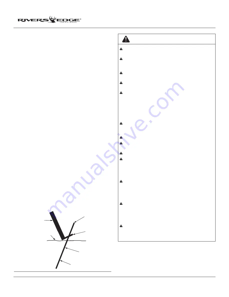
4.  Drive (4) ground stakes (not included) through the holes in 

the (4) feet. Stakes should be approximately 24” in length 

with 18” in ground and should be driven in at an angle.  

SEE FIGURE 15

5.  Climb ladder slowly and carefully always having three 

points of contact on ladder at all times. Lean forward, 

towards ladder as you climb. Be sure hands are free for 

climbing. 

6.  Upon reaching foot platform, with shooting rail flipped 

back out of the way, carefully turn around and sit on seat.

  NOTE: To exit your ladder pod, reverse the climbing 

procedure. Take great care to be sure of hand and foot 

placement as you proceed back down pod ladder.

7.  Reverse uprighting and use instructions to take ladder pod 

down.

FIGURE 15

LEG

GROUND LEVEL

 6 ”

 ABOVE

GROUND

FOOT

  TAB

GROUND STAKE

DRIVEN 18 “ 

BELOW GROUND

AT AN ANGLE

3/8” (ROD) STAKES X 24” LONG

           (NOT INCLUDED)

WARNING

Double check assembly steps to be certain you have 

correctly assembled this product.
Study your new stand to become familiar with all of its 

features and design. Save these instructions for future 

reference. 
Be Sure uprighting area is open, flat, level, and dry with 

no power lines near!
Always use at least four (4) people to install or take down 

a free standing platform.
Do Not use any type of motorized vehicle to upright this 

free standing platform stand. You could cause unnecessary 

damage to this product. Upright by hand only using four 

people, two people at feet end of free standing platform 

stand and two people at platform end. Be aware it is top 

heavy. Use great care and caution during this process to 

prevent an off balance fall to prevent injury.
As free standing platform stand goes over-center, be sure 

to slowly allow the stand to land on the opposite leg 

sections. Be Sure all people are clear to prevent injury.
Never stand on seat, it is designed for sitting only.
If seat is removable, be certain it is securely attached 

when in use.
Always lean forward as you climb ladder or climbing aid.
Always maintain three (3) points of contact when 

climbing a ladder treestand or free standing platform 

stand. Proper three-point contact means having either 

two feet with one hand or one foot with two hands on 

the step portion of the ladder or climbing aid at all times.
Always wear the appropriate footwear when using a free 

standing platform stand. A good non-slip safety boot is 

important to your personal safety. Be especially careful 

that boot laces do not get hooked on the stand or any of its 

components (tuck shoelaces into boots before climbing).
Some models include a shooting rail. Never lean against, 

lean over, or sit on shooting rail. It is designed as a shooting 

rest only. On models that have a non-fixed shooting rail, 

be sure shooting rail is flipped back or swung to the side 

when ascending or descending ladder.
Some models include a footrest, which is designed as a 

footrest only. Never stand on footrest! Always be fully 

aware of foot placement.

Summary of Contents for RE741 Perimeter

Page 1: ...ual RE741 Perimeter Ladder Pod GAS OIL RATIO 50 1 P N 17781 REV3 03 29 16 2016 RETI All Rights Reserved Get parts online at www HuntRiversEdge com PARTICIPATING MEMBER PRODUCT MEETS INDUSTRY STANDARDS...

Page 2: ...formed by RETI To obtain warranty service and or replacement instructions you must obtain prior approval from RETI before shipping your package to us by calling our customer service department at 800...

Page 3: ...signal device such as a mobile phone radio whistle signal flare or personal locator device PLD must be on your person and readily available at all times Inspect the treestand or free standing platfor...

Page 4: ...es should be 3 8 inch rod x 24 inches long INSPECTION AND MAINTENANCE SCHEDULE BEFORE EACH USE PERFORM THE FOLLOWING Inspect all webbing rope cord and strap assemblies for wear or damage Inspect cable...

Page 5: ...hten any nut and bolt combinations completely until all parts are assembled together Finger tighten plus one turn of a wrench only This will temporarily hold the lock nut on the bolt while helping ali...

Page 6: ...uction when swivel is pivoted during use 6 Attach factory assembled seat 16857 to the swivel using 4 provided 1 4 20 x 1 1 4 bolts and locknuts SEE FIGURE 5 NOTE Make sure head of bolts are on swivel...

Page 7: ...142 to the backrest frame using 2 provided 1 4 20 x 2 1 2 bolts locknuts and plastic washers SEE FIGURE 8 11 Attach the shooting rail front rail to the shooting rail side rails using 2 provided 1 4 20...

Page 8: ...ttach them to the assembled platform in the following order attach top ladder SL51 ladder onto the J receiver tubes attach middle ladder SL51 ladder onto the top ladder attach bottom ladder TP159 ladd...

Page 9: ...TP147 into the middle leg pockets NOTE Make sure foot pads are orientated out away from platform 17 Secure top legs to the leg pockets attached to platform using 2 provided 1 4 20 x 2 1 4 bolts and lo...

Page 10: ...ale cross braces TP131 Insert the male cross braces into the female cross braces Use 2 provided 1 4 20 x 1 1 4 bolts and locknuts to secure these cross braces in the hole location to achieve length C...

Page 11: ...ger tightened 5 16 18 x 1 1 4 bolts and locknuts SEE FIGURE 11 and 12 NOTE Make sure to use the 1 1 4 bolts and nuts to attach cross braces at the leg joint that is already holding the diagonal braces...

Page 12: ...heck for parts online at www HuntRiversEdge com or call 800 450 EDGE 3343 M F 8 5 12 FIGURE 12 DETAIL VIEW CROSS BRACE C CROSS BRACE A CROSS BRACE E 5 16 18 X 3 4 BOLT 5 16 18 X 1 1 4 BOLT 5 16 18 x 3...

Page 13: ...e com or call 800 450 EDGE 3343 M F 8 5 13 Operators Manual RE741 Perimeter Ladder Pod FIGURE 13 5 16 18x3 4 BOLT LOCKNUT 5 16 18x3 4 BOLT LOCKNUT DETAIL VIEW CROSS BRACE C CROSS BRACE A CROSS BRACE E...

Page 14: ...4 provided 1 4 20 x 2 bolts locknuts and washers You must now tighten all nut bolt assemblies securely DO NOT crush tubing when tightening f The side of curtain with numerous Velcro loops is the top s...

Page 15: ...OUND AT AN ANGLE 3 8 ROD STAKES X 24 LONG NOT INCLUDED WARNING Double check assembly steps to be certain you have correctly assembled this product Study your new stand to become familiar with all of i...

Page 16: ...adder Pod Check for parts online at www HuntRiversEdge com or call 800 450 EDGE 3343 M F 8 5 16 ILLUSTRATED PARTS BREAKDOWN DETAIL A 24 12 4 9 11 1 13 18 7 32 11 17 27 4 1 26 19 20 25 12 23 DETAIL A 9...

Page 17: ...for parts online at www HuntRiversEdge com or call 800 450 EDGE 3343 M F 8 5 17 Operators Manual RE741 Perimeter Ladder Pod ILLUSTRATED PARTS BREAKDOWN 31 22 21 34 39 40 38 37 5 8 15 6 14 2 10 3 33 30...

Page 18: ...TP100 PLATFORM 2 16 TP109 RECEIVER 2 17 TP113 FOOT PAD 2 18 TP115 BRACKET SUPPORT BAR 6 19 TP131 BRACE FEMALE CROSS 60 8 20 TP132 BRACE MALE CROSS 36 2 21 TP142 SIDE SHOOTING RAIL 2 22 TP143 FRONT SHO...

Page 19: ...Bolts shown are for size reference only Extra hardware may be included in the parts bag 1 4 20 x 1 1 4 Grade 5 Hex Head Bolt 1 4 20 x 1 1 2 Grade 5 Hex Head Bolt 1 4 20 x 1 3 4 Grade 5 Hex Head Bolt 1...

Page 20: ...sedge com All weights specifications and features are approximate and are subject to change without notice Due to continuous product improvements product images may not be exact Warning labels in some...

Reviews: