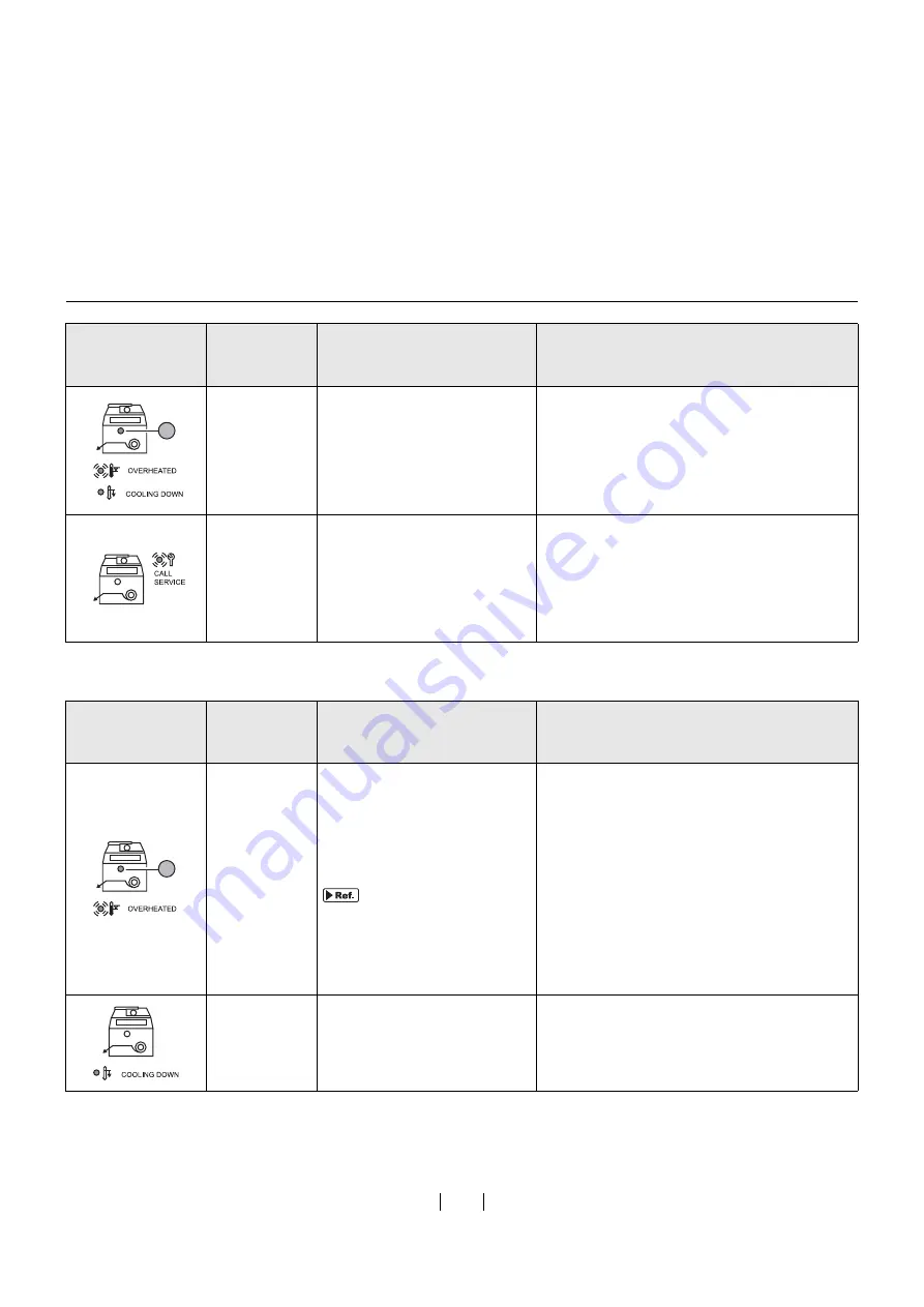
Riso GOCCOPRO 100 User Manual Download Page 66

64

Other Indications

P-90

Overheating of the Thermal 
Print Head.

Pre

ss

 the <ALL RESET> Key to cancel the error.

The indicator change

s

 from blinking (lit) to not 

light.
The <COOLING DOWN> Indicator i

s

 lit, and 

the cooling-down operation i

s


s

tarted. When 

the <COOLING DOWN> Indicator ha

s

 gone 

o

u

t, the 

s

creen making can be re

su

med.

P-xx

Service Call Error occ

u

rred.

Try one of the following action

s

.

• Pre

ss

 the <ALL RESET> Key to cancel the 

error.

• T

u

rn off the machine, and then t

u

rn on the 

machine.

When the machine doe

s

 not operate de

s

pite 

the above action, contact yo

u

r dealer.

Error Location 
Indicator/Error 

Type Indicator

Error No.

Error Description

Action

F-

3

4

Exce

ss

ive cover ratio.

The Thermal Print Head may 
be overheated d

u

ring 

s

creen 

making.

"The Screen Making 
Length and cover 
Ratio" on page 44

To continue screen making

Pre

ss

 the <START> Key.

To stop screen making

Perform the following action

s

.

1.

Pre

ss

 the <ALL RESET> Key to cancel the 

error.

2.

Pre

ss

 the <ONLINE> Key to 

s

witch to offline 

mode, and delete the data in the 

s

creen-

making q

u

e

u

e.

3.

Pre

ss

 the <ONLINE> Key again to ret

u

rn to 

online mode.

None

The temperat

u

re of the Thermal 

Print Head ro

s

e.

The Thermal Print Head i

s

 being cooled down.

When the <COOLING DOWN> Indicator goe

s


o

u

t, the next 

s

creen making can be 

s

tarted.

Error Location 
Indicator/Error 

Type Indicator

Error No.

Error Description

Action

3

3

Summary of Contents for GOCCOPRO 100

Page 1: ...User s Guide 053 36001 053 36003 Printed in Japan 2020 2...

Page 2: ...rning the equipment off and on the user is encouraged to try to correct the interference by one or more of the following measures Reorient or relocate the receiving antenna Increase the separation bet...

Page 3: ...rosoft Corporation in the United States and or other countries Other corporate names and or trademarks are either registered trademarks or trademarks of each company respectively The screens and conte...

Page 4: ...body that can be placed beside the desk Characteristics of This Product This machine is a digital screen maker exclusively designed for RISO Digital Screen Master The imaged screen can be attached on...

Page 5: ...e screen master well 1 Turn the wheel beside the Screen Master Guide Flap inward to raise the Screen Mas ter Guide Flap 2 Pull out the Screen Master Roll up to the line indicated by the arrows 3 Close...

Page 6: ...on Connection 10 Precautions for Connecting with the Power Supply 10 The Power Cord and an Extension Cable 10 The Printer Driver 10 Precautions on the Connection with a Computer 10 Precautions on Use...

Page 7: ...en 1 Preparing the Machine 34 2 Transmitting Original Data from the Computer 35 Details of Printer Driver Settings 36 3 Selecting a Frame 40 Selecting a Frame and Starting Screen Making 40 3Settings f...

Page 8: ...8 75 USB Connection 75 Network Connection LAN 76 For Windows 7 77 USB Connection 77 Network Connection LAN 78 For Windows XP 79 USB Connection 79 Network Connection LAN 80 For Windows Vista 81 USB Cab...

Page 9: ...Introduction This section describes matters you should know before using the machine and precautions you should follow...

Page 10: ...sion cord must be within 14 75 feet 4 5 m and 15 feet 5 m respectively If the Voltage Changeover Switch is in the 220 V to 240 V position when using the machine use a cable with specifications of 250...

Page 11: ...re or elec tric shock If the machine emits excessive heat smock or foul odor immediately turn off the POWER unplug the power cord and contact your dealer Failure to do so can result in fire or electri...

Page 12: ...250 V 5 A or more The Printer Driver This printer driver is designed for screen making by trans mitting original data from your computer The printer driver is contained in the included CD ROM When mak...

Page 13: ...changes Hot and humid locations or cold and dry locations How to Produce an Imaged Screen from Original Data other than of Standard Size To specify an original size other than the standard size be su...

Page 14: ...alculated based on the size or length of the frame used and the size of the original data The size of the margin required for each frame type is as indicated in the table below The frame used can be s...

Page 15: ...he margin is set in Custom Setting mode How to Register a Frame on page 50 MANUAL Arbitrary Margin 2 4 to 8 0 60 mm to 200 mm 0 6 to 8 0 15 mm to 200 mm Select the Top side or the End side of the orig...

Page 16: ...this port using a commercially avail able USB cable USB cable Connection on page 22 6 Screen Making Unit Cover Opens to allow screen master replacement and mainte nance of the machine interior Setting...

Page 17: ...een Making Unit 10 Screen Master Guide Flap 11 Screen Master Roll Holder Secures a Screen Master 12 Screen Master Roll 13 Power Connector 14 Voltage Changeover Switch You can switch the input voltage...

Page 18: ...2 3 ALL RESET Key Used to return the setting made on the Control Panel to the initial set value or cancel trouble after troubleshooting is completed 4 STOP Key Stops the operation being executed Press...

Page 19: ...ing mode in which the initial set tings can be changed 18 CUSTOM SETTING Key Press it to enter or exit Custom Setting mode How to Make Settings in Custom Setting Mode on page 49 Switching to offline w...

Page 20: ...ON Turning on the machine 1 Preparing the Machine on page 34 Creating original data on the computer and outputting the data data transmission 2 Transmitting Original Data from the Computer on page 35...

Page 21: ...ions for Use for the First Time To use the machine for the first time after installing it the following preparations must be made Setting a New Screen Master Roll page 20 Installing the Printer Driver...

Page 22: ...n Master Roll Set a Screen Master Roll in the machine If the REPLACE MASTER Indicator on the Control Panel is lit also perform the fol lowing procedure to replace the screen master For the Screen Mast...

Page 23: ...ard to rewind 8 Close the Screen Making Unit 9 Close the Screen Making Unit Cover Do not remove the wrapper yet mark must be seen on the left Do not remove the wrapper 1 1 1 2 2 2 If you cannot insert...

Page 24: ...ction describes how to install the printer driver for windows supporting the Plug Play installation when your computer and the machine are connected via USB cable To install the printer driver it is n...

Page 25: ...language from the drop down list 2 Click OK 4 When Before installation dialog box appears click Next For Windows 7 64 bit Windows Vista 64 bit Proceed to step 18 5 1 Select Connect via a USB cable 2...

Page 26: ...r of the machine is lit and press the START Key A test pattern is transferred onto a screen using Frame 1 frame length 23 2 590 mm 14 Check if the test pattern was correctly trans ferred onto a screen...

Page 27: ...d The following procedures are only applied for Windows 7 64 bit Windows Vista 64 bit 18 1 Select Use another connection method 2 Click Next 19 When Target Printer Selection dialog box appears click C...

Page 28: ...es is selected 2 Click Next 24 When Ready to install dialog box appears click Install Installation is started 25 When USB Port Settings dialog box appears click Next This USB is the name of the port c...

Page 29: ...pps screen and click Control Panel Hardware and Sound Devices and Printers 31 Open the properties of the printer to which the Printer Driver has been installed Right click on the icon of printer and s...

Page 30: ...t pattern was not correctly transferred onto a screen see Troubleshooting Tips on page 65 35 After the computer is rebooted remove RISO GOCCOPRO Printer Driver CD ROM from the CD ROM drive of your com...

Page 31: ...Properties in the upper part of the dia log box For Windows Vista 1 Click Start icon Control Panel Hardware and Sound Printers and open Printers folder 2 From a menu that appears as you right click o...

Page 32: ...Click Start enter Device Manager in the Search programs and files then click Device Manager 3 Click View in the menu and place a checkmark in the Show hidden devices checkbox 4 Click Printers in the l...

Page 33: ...of the Installation Proce dure on page 23 2 1 Click Use another connection method 2 Click Next Network Connection LAN To connect the machine to a LAN the optional RISO Network Card is required Use a...

Page 34: ...ick Next 5 Perform steps 10 to 17 of the Installation Proce dure on page 24 The machine is now ready for use When selected printer driver has already been installed Installation Method dialog box appe...

Page 35: ...data created on your computer onto a screen with this machine Prepare original data on your computer in advance To reproduce a screen perform steps of 3 Selecting a Frame from page 40 1 Preparing the...

Page 36: ...Indicator on the Con trol Panel is lit When the ONLINE Indicator is not lit press the ONLINE Key to switch to online mode 1 Preparing the Machine ON When the REPLACE MASTER Indicator is lit set a new...

Page 37: ...ine 2 Transmitting Original Data from the Computer Transmit original data created on your computer to the machine You can change settings such as image quality using the printer driver before trans mi...

Page 38: ...an imaged screen 2 Original size Specify the size and direction portrait landscape of the original data Details of Printer Driver Settings Image Setting tab Specify the same size as the original size...

Page 39: ...nes Initial value 38 lines Screen angle The angle at which dots are arranged can be set Adjusted if moire interference pattern occurs Unit degree Setting range 0 to 90 degrees Initial value 37 degrees...

Page 40: ...e check box edge enhancement is applied to the image to accent contours Tone smoothing When Screen covered is selected for Screening type the tonal expressions used in screen covered processing are sm...

Page 41: ...n t adjust the text thickness These text processes can be performed only if text information is contained in the original and the font type can be changed 8 Restore default Returns all settings to the...

Page 42: ...Press the FRAME SELECT Key to select a frame to be used You can select the frame from the frames registered in FRAME SELECT in Custom Setting mode MINIMUM and MANUAL The indicator of the selected fra...

Page 43: ...to 9 Keys To stop screen making press and hold the STOP Key 1 second or more and then released The screen making is stopped and the cut screen is ejected from the Imaged Screen Outlet However if the S...

Page 44: ...nt Head lowers and the COOLING DOWN Indicator goes out When the machine receives the original data that is expected to overheat the Ther mal Print Head due to conditions such as the cover ratio of the...

Page 45: ...cator is lit after the screen making is completed Wait to perform the next screen mak ing until the COOLING DOWN Indi cator goes out 3 Screen making interrupted The OVERHEATED Indicator blinks Press t...

Page 46: ...10 0 3 937 7 874 11 81 15 75 19 69 23 62 27 56 31 50 100 200 300 400 500 600 700 800 Cover ratio Overheating warning F 34 will not be displayed Overheating warning F 34 will be displayed Screen making...

Page 47: ...gs when the machine is turned on in Custom Setting mode or registering an arbitrary frame size in advance Changed settings are effective until they are changed again in Custom Setting mode Settings th...

Page 48: ...n register the margin size on the End side when MINIMUM is selected in FRAME SELECT on the Control Panel The margin size on the Top side is 2 4 60 mm fixed 0 6 15 mm to 1 2 30 mm 1 2 30 mm 7 Frame sel...

Page 49: ...creen is displayed 31 Screen Running Counter The value dividing the total length of the imaged screen by 16 5 420 mm is displayed 40 Image expan sion contraction When an image happen to be expanded co...

Page 50: ...all settings For details see Initializing the Custom Setting Mode the Network Card on page 54 99 Custom Setting Mode Initializa tion Returns the setting to the fac tory default setting For details see...

Page 51: ...m Setting mode can be made on the Control Panel of the machine You can set the IP address for the RISO Network Card For details see How to Set the IP Address on page 52 For how to register frame sizes...

Page 52: ...tween 8 0 to 47 2 200 mm to 1200 mm Any frame whose outer size is outside the following range cannot be registered Frame length Screen length 1 2 Margin size on the Top side 2 3 Original data length 4...

Page 53: ...ct the entered frame length press the C Key to delete the entered value Pressing the CUSTOM SETTING Key before pressing the ENTER Key cancels the setting and returns the machine to normal mode Pressin...

Page 54: ...dress using RISO ADMIN included with the RISO Network Card Set it using the Control Panel of the machine To correct the entered item number press the C Key to delete the entered value If you cannot ex...

Page 55: ...far left To correct the third number press the C Key to delete the entered value Pressing the CUSTOM SETTING Key before pressing the ENTER Key cancels the setting and returns the machine to normal mod...

Page 56: ...r goes out The Custom Setting mode is initialized and the machine returns to normal mode Initializing the Custom Setting Mode the Network Card Returns all settings of the Custom Setting mode and the n...

Page 57: ...ils to make settings see How to Make Settings in Custom Set ting Mode on page 49 Setting No Setting setting range Setting No Setting setting range 0 2 00 13 1 25 1 1 75 14 1 50 2 1 50 15 1 75 3 1 25 1...

Page 58: ...MEMO 56...

Page 59: ...Maintenance Maintenance page 58 Cleaning page 59...

Page 60: ...nauthorized persons to make adjustment or repairs The machine has precision moving parts inside Do not handle the machine in any other way than described in this guide Be careful of the edge of metal...

Page 61: ...dle and open the cover 2 Hold the Screen Making Unit Open Lever tightly and open the Screen Making Unit Cleaning The quality of imaged screen may suffer if the Thermal Print Head of the Screen Mak ing...

Page 62: ...oft cloth or tissue several times to remove stains Setting a New Screen Master Roll on page 20 To prevent stains from adhering to the main unit gently wipe the whole body with a neutral detergent on a...

Page 63: ...hooting This section describes the cause and an action to be taken when the Error Indicator lights or the machine does not normally operate When an Error Indicator Lights page 62 Troubleshooting Tips...

Page 64: ...pe Indicator Error No Error Description Action A 01 A screen master has not been fed correctly Remove the Screen Master Roll and set it cor rectly again Setting a New Screen Master Roll on page 20 A 1...

Page 65: ...Cover If the screen master has been wrinkled or cut at an angle cut the edge of the screen master straight and then set it again Setting a New Screen Master Roll on page 20 None The Screen Making Uni...

Page 66: ...tion Indicator Error Type Indicator Error No Error Description Action F 34 Excessive cover ratio The Thermal Print Head may be overheated during screen making The Screen Making Length and cover Ratio...

Page 67: ...aster and set it correctly Setting a New Screen Master Roll on page 20 Part of the original data transferred onto the imaged screen is miss ing The size of the original data may exceed the image area...

Page 68: ...with scissors 6 Turn on the power switch 7 Rewind the screen master and set it again Setting a New Screen Master Roll on page 20 The START indicator is lighting The original data was received in the s...

Page 69: ...1 Cancel the transmission from your computer 2 Turn off the machine 3 Correctly connect the cable again 4 Turn on the machine Do the settings of the application soft ware original size original direc...

Page 70: ...support the machine is selected graphics may not be transferred correctly onto the screen After selecting the driver supporting the machine edit the original data and produce an imaged screen again I...

Page 71: ...s you can enter You can enter up to 30 characters Width or Length can not be entered in the Original size entry dia log box Did you try to enter a value that exceeds the setting range The original siz...

Page 72: ...70 MEMO...

Page 73: ...Appendix Registering Original Size page 72 Manually Installing the Printer Driver page 73 Uninstalling the Printer Driver page 83 Consumables and Options page 86 Specifications page 87...

Page 74: ...nal size is displayed in the list of standard original sizes 7 In the Original size entry dialog box click Close 8 Click OK The registration of the original size is now com pleted Registering Original...

Page 75: ...ies and click Next 11 Click Close and reboot your computer 12 Click Control Panel Hardware and Sound Devices and Printers 13 Right click RISO GOCCOPRO Series and select Printer Properties 14 Click Pri...

Page 76: ...t the following inf file from Browse and click OK For Windows 10 32 bit CD ROM Windows 32 bit Driver WinVista_8 English RISODRV INF For Windows 10 64 bit CD ROM Windows 64 bit Driver WinVista_8 Englis...

Page 77: ...ws 64 bit Driver WinVista_8 English 10 Select RISO GOCCOPRO Series and click Next 11 Click Close and reboot your computer 12 Click Control Panel Hardware and Sound Devices and Printers 13 Right click...

Page 78: ...wing inf file from Browse and click OK For Windows 8 1 Windows 8 32 bit CD ROM Windows 32 bit Driver WinVista_8 English RISODRV INF For Windows 8 1 Windows 8 64 bit CD ROM Windows 64 bit Driver WinVis...

Page 79: ...2 bit Driver WinVista_8 English For Windows 7 64 bit CD ROM Windows 64 bit Driver WinVista_8 English 10 Select RISO GOCCOPRO Series and click Next 11 Click Close and reboot your computer 12 Click Cont...

Page 80: ...ct the following inf file from Browse and click OK For Windows 7 32 bit CD ROM Windows 32 bit Driver WinVista_8 English RISODRV INF For Windows 7 64 bit CD ROM Windows 64 bit Driver WinVista_8 English...

Page 81: ...Next 9 Click Finish 10 Reboot your computer 11 Open the Printers folder and open the proper ties of the installed printer driver 12 Click Print Processor on the Details tab 13 Click R35X8EP from the l...

Page 82: ...stalled CD ROM Windows 32 bit Driver WinXP English RISODRV INF 6 Select RISO GOCCOPRO Series and click Next 7 Transfer the test page onto a screen and check that the original data is correctly transfe...

Page 83: ...ick Browse and select the inf file of the driver to be installed For Windows Vista 32 bit CD ROM Windows 32 bit Driver WinVista_8 English RISODRV INF For Windows Vista 64 bit CD ROM Windows 64 bit Dri...

Page 84: ...our computer s CD ROM drive 5 Click Have Disk and select the inf file of the driver to be installed For Windows Vista 32 bit CD ROM Windows 32 bit Driver WinVista_8 English RISODRV INF For Windows Vis...

Page 85: ...l 6 Click Finish When uninstalling the printer driver be sure to reboot the computer Checking the Reboot the PC Now checkbox will reboot the computer after Fin ish is clicked Uninstalling the Printer...

Page 86: ...GOCCO PRO Series and click Remove 5 When the Remove Driver and Package dialog opens Remove driver and driver package to delete the driver and driver package For Windows XP 1 Select Printers and Faxes...

Page 87: ...lick Delete from the displayed menu 3 Right click on the margin of the Printers folder and click Run as administrator Server prop erties from the displayed menu 4 Click the Driver tab 5 Select RISO GO...

Page 88: ...ne text and solid image RISO DIGITAL SCREEN MASTER 200P 32 12 This screen master is 200 mesh per inch type for water based ink and solvent type ink Appropriate for fine quality printing on the materia...

Page 89: ...o 200 mm on the Top side 0 6 to 8 0 15 mm to 200 mm on the End side Screen length Minimum 3 3 85 mm when image area length 0 39 10 mm and frame setting MINIMUM minimum margin 2 4 60 mm on the Top side...

Page 90: ...er supply 100 120V 3 0A 220 240V 1 2A 50 60 Hz Power consumption Approx 200 W Main unit size During use 23 13 16 W 25 19 32 D 15 5 32 H 605 mm W 650 mm D 385 mm H During storage 19 11 16 W 25 19 32 D...

Page 91: ...alling the Printer Driver 22 IP address settings 52 L Line art style 38 M Maintenance 58 Manually Installing the Printer Driver 73 Margin Size 12 Margin size on the End side 13 41 50 Margin size on th...

Page 92: ...n 2 Screen covered 38 Screening type 37 Selecting a Frame 40 Setting a New Screen Master Roll 20 Slim 39 Solid look 38 Specifications 87 T Text style 39 The Margin Size Required for Screen Making 12 T...

Page 93: ......

Page 94: ...Printed in Japan 2020 2...

Reviews: