3. Tighten the adapter and use set screws to attach the adapter to the cage nuts in the top of the
ticker.
4. Repeat for each of the support points for that section.
Connecting Sections
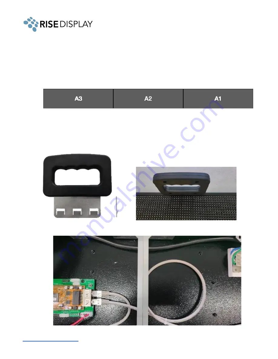
1. Align all sign sections as diagrammed below. A1 is the master section with the controller and
WIFI data receiver. It should be positioned at the far right, starting point.
2. Remove the module on both ends of each section. Insert the handle into the top between the
chassis and module, make sure the spring is facing the module and pull out. The module is fixed
by five magnets attached to the frame at the top, and after loosening you can lift the module out
of the track holding the bottom in place.
3. Connect the RJ45 data cable between sections A1 and A2
7


