Rinnai Corporation ES17 / ES22 Manual
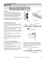
Pipe stopper A
Flue Manifold
Sliding tube
Hook
Pipe stopper A
Connecting the Appliance
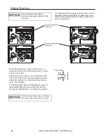
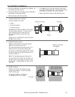
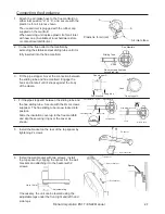
1. Attach the air intake hose to the flue manifold on
plastic tie for air inlet as shown.
either inlet position “a” or “b”, and secure with the
The unused inlet is plugged with the rubber cap
supplied on the manifold.
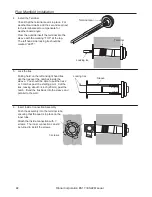
3. Fit the pipe stopper A over the connection between
the sliding tube and flue manifold. Engage the
hook and rotate it until it snaps against the body
of the clamp.
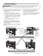
Slide the insulation cover up to the flue manifold
and slip the securing ring over the cover as
shown.
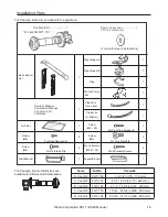
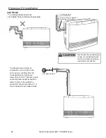
5. Install the bracket on the rear of the top spacer by
tightening 2 screws.
6. Install the wall bracket with two screws. Install
the top spacer by clipping the spacer into the wall
brackets and attaching it to the heater with 2
screws.
a
b
Air inlet elbow
Plastic tie for air inlet
When servicing unit replace plastic tie for air inlet
with new one. (Available at local hardware store
or contact local distributor.)
2. Connect the flue outlet to the manifold by
extending the stainless steel sliding tube until it is
fully inserted into the flue manifold.
4. Fit the pipe stopper B between the sliding tube and
the flue sliding tube. Secure with the 4mm screws
supplied. The flue sliding tube is now locked into
position.
Sliding Tube
Slide
Do not extend flue tube
beyond red line.
Flue Manifold
Flue sliding tube
Sliding tube
Flue Manifold
Pipe stopper A
Screw
Pipe stopper B
Cover
Slide to here
Fit Ring
Slide insulation Cover
If necessary, the unit can be leveled using the
adjustable legs under the front right and left hand
side legs.
Adjustable Leg
Up to 10 mm
Spacer bracket
Top spacer
Top spacer
Wall bracket
Spacer bracket
Spacer

