


10
Rinnai Corporation ES17 / ES22 Manual
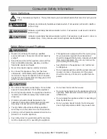
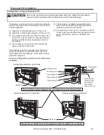
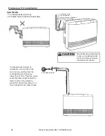
CAUTION
Prevent dust from
accumulating on the power
cord, side covers, and parts
behind the appliance.
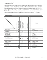
Care and Maintenance
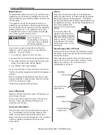
Filters
Dirty filters reduce the air flow and the appliance’s
ability to produce heat. The filters should be cleaned
frequently during the heating season. If the filters
become blocked the filter indicator lamp will flash and
the appliance will beep. Eventually the appliance will
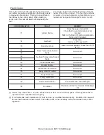
turn off and display fault
code 14 on the control panel
display.
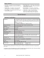
To clean the filters, the
appliance should be OFF
and cool. Remove the filter
and clean it using a soft dry
cloth or vacuum. If the filter
is greasy wash with warm
soapy water, rinse, and dry
completely.
Maintenance
All maintenance and service are to be performed by a
qualified service technician, preferably one who has
attended Rinnai service training classes on the Direct
Vent products.
The appliance should be inspected annually by a
qualified service technician. More frequent cleaning
may be required due to excessive lint from carpeting,
bedding material, etc. It is imperative that control
compartments, burners, and circulating air passage
ways of the appliance be kept clean.
Any screen or guard removed for servicing the
appliance must be replaced prior to operating the
appliance. Clean as follows:
1. Turn heat off. Allow to cool for one hour.
2. Remove the front panel by removing eight screws.
3. Use pressurized air to remove dust from the main
burner, heat exchanger, and fan blades.
4. Use soft dry cloth to wipe cabinet.
Do not use wet cloth or spray cleaners on the burner.
The flue should be inspected annually for blockages or
damage.
Motors are permanently lubricated and do not need
periodic lubrication. Keep fan and motor free of dust
and dirt by cleaning annually.
Verify proper operation after servicing.
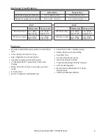
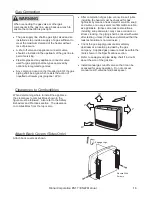
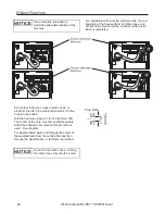
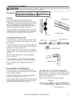
Visual Inspection of Flame
Check that the burner flames are operating normally.
The flame can be seen through the circular window
through the louvers.
When operating normally the burner flame should
appear as long, clear, blue, stable, streaks. Yellow
flames or an orange color is abnormal and
maintenance is required.
Care of Exterior
Dampen soft cloth with warm water. Wring water out
well and wipe the unit.
Do not use volatile substances such as benzene or
thinners. They cause fading of the paint and
deformation of the resin.
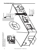
Snow Accumulation
Keep the area around flue terminal free of snow and
ice. The appliance will not function properly if the
intake air or exhaust is impeded by obstructions.
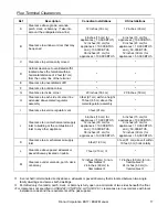
Refer to the Flue Terminal Clearances. The clearance
in Ref. A should be maintained from any snow
accumulation.
NORMAL
Flame Rod
Long, clear, blue,
stable flames
ABNORMAL
Yellow flames or
orange color
Flame Rod