21
OPERATION
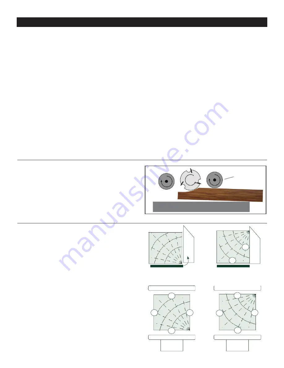
SNIPE
The term 'snipe' refers to the depression that may occur
at the front or rear of a board during planing. It is caused
by uneven pressure on the cutterhead when a board is fed
into the planer, or when exiting. FIG. 45.
Avoid snipe by keeping your lumber firmly down onto the
planer bed at the beginning of the cut, and also at the end
of the cutting action, as the lumber exits the planer.
FIG. 45
3. Set planing thickness. Measure your board's thickness
and set the planer to this measurement, or 1/16" under this
figure. For the initial pass, you do not want to take off an
excessive amount of stock (over 1/8"), or damage to the
planer may result. Repeated passes through the planer will
get you to your final desired board thickness. See page 14.
4. Feed boards slowly and straight into the planer. Boards
will be automatically fed through the planer by the infeed
and outfeed rollers.
- Guide work pieces straight into and through the planer.
The cutting action of the cutterhead may try to turn a board
being surfaced, so slight controlling of the board may be
necessary. Do not push the board forward, let the planer's
rollers automatically move the board through the machine.
5. Remove the board from the planer. Ref: Step 2, Do not
pull the lumber as it exits the machine. Let the out-feed
roller move the work piece out of the planer at its own rate,
but support the lumber as it extends past the extension
rollers, if needed.
Planer Operation - Continued from page 20
- Make sure that there are no loose knots, nails, staples,
dirt or foreign objects in the wood to be planed.
- Surface wood in the same direction of the grain, not
across the grain. Never plane end cuts or end grain.
- Do not plane boards that are less than 12" long. Short
boards should be planed end to end with other boards to
prevent kick-back and snipe.
- Boards longer than 60" should have additional support
as they enter and exit the planer, so that they do not tip up
or down, causing snipe on the ends.
- Run boards through the planer at different positions
along the width of the bed to utilize the full length of the
cutting knives. Planing only in the center, or through one
side of the planer, will quickly dull the knives in that area.
- To thickness plane stock with surfaces are not parallel,
use suitable feeding aids (make fitting templates).
SQUARING A WORK PIECE EXAMPLE
1. FIG. 46, A - On the jointer, surface side 1 flat.
2. B - After surfacing side 1, turn the work piece 90º so
that side 1 now rests against the fence. Joint side 2 flat.
The work piece will now have two sides at 90° to each
other.
3. C - Using the planer, run the work piece with side 1
positioned flat against the planer bed. The opposite side 3
can then be cut, and it will then be parallel to side 1.
4. D - Position side 2 flat against the planer bed, and side
4 will be planed flat, and be parallel to side 2.
The work piece will now be square, having four flattened
surfaces and four square edges.
1
2
FENCE
90º
1
FENCE
JOINTER
JOINTER
PLANER
BED
PLANER
BED
CUTTERHEAD
CUTTERHEAD
4
1
2
3
4
3
2
1
A
B
C
D
FIG. 46
FEED
ROLLER
PLANER BED
Summary of Contents for 25-010
Page 31: ...31 WARRANTY...


