


18
ADJUSTMENTS
THE MACHINE MUST NOT BE
PLUGGED IN AND THE POWER SWITCH MUST BE IN
THE OFF POSITION UNTIL ALL ADJUSTMENTS ARE
COMPLETE.
START BUTTON
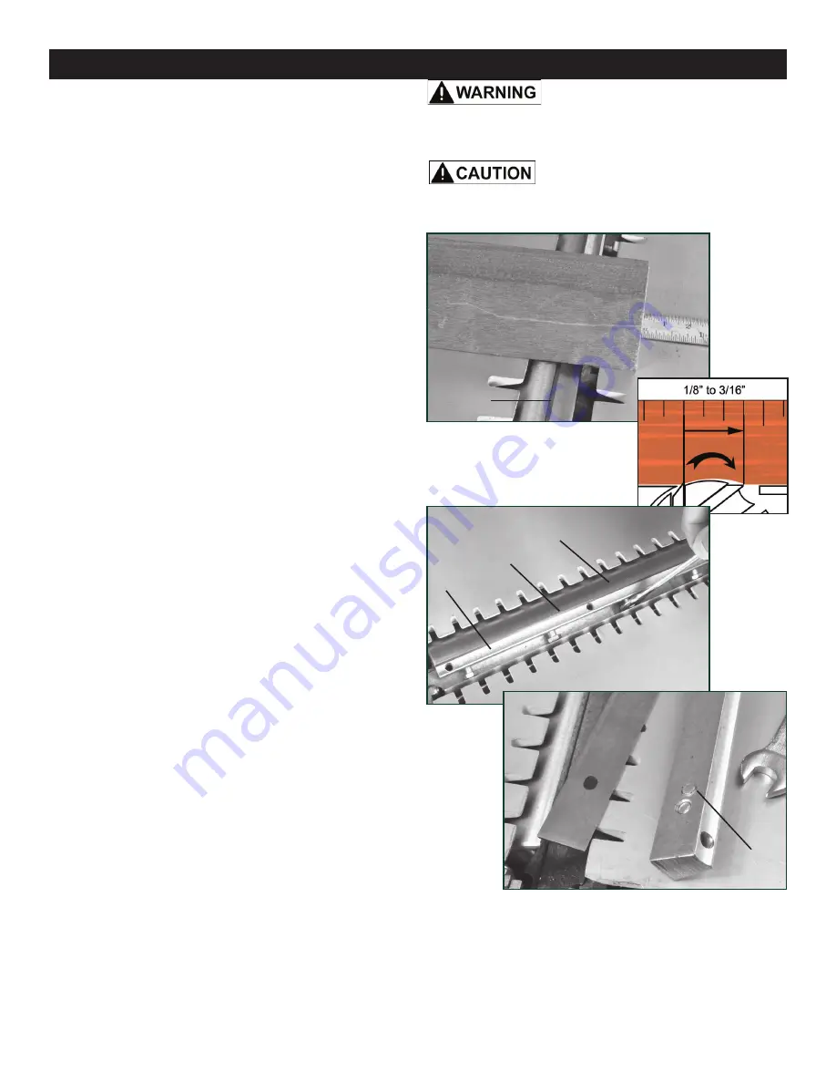
REPLACING PLANER KNIVES
REMOVING PLANER KNIVES
1. Unplug the machine and put the power switch in the
OFF position until all adjustments are complete.
2. Remove the jointer fence assembly.
3. Raise the cutterhead guard and
remove the guard
(#207) to get full access to the cutterhead and knives.
4. Loosen the Lockbar (#102) in the block with the 10mm
hex head Lockbar ‘Grub’ Screws (#101). FIG. 36.
5. R
emove the lockbar FIG. 36, A and the attached planer
knife (B) from the cutterhead (C).
6. Clean all surfaces of the cutterh
ead and planer knife
lockbar.
INSTALLING THE PLANER KNIVES
7. Install the new planer knife onto the back of the lock-
bar. Make sure that both positioning pins on the lockbar
fit into the matching holes on the plane
r knife FIG. 37.
NOTE:
The 25-010 planer blades (#105) are reversible! Both
front and back edges are sharpened. Just flip to change.
8. Place the lockbar with the mounted knife back into the
cutterhead. Make sure that the lockbar is centered in the
cutterhead block.
NOTE:
Take care that the knife does
not slip off of the two pins during this step.
9.
Tighten the four Lockbar Grub Screws to secure the
set knives in the cutterhead.
NOTE:
To prevent distor-
tion of the lockbar and knife, start with tightening the grub
screw in the center, then move out to the side screws.
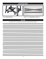
SETTING THE PLANER KNIVES - method 2
This method involves using a ruler, and a piece of wood or
aluminium straight edge, preferably one with a wide body.
1. Place the straight edge at either side of the cutterhead,
resting on both feed tables.
FIG. 34.
2. Slowly turn the cutterhead by hand, in the direction of
the cutting knives. If the planer knives are set correctly, the
end of the straight edge is moved forward 1/8” to 3/16”.
FIG. 35. If
the straight edge moves less than 1/8”, the
knives are set too low. If it moves further than 3/16”, they
are set too high.
3. Se
e Page 17, steps 2-4, for
information on how to
loosen the retaining screws to make knife adjustments.
4. This procedure must be performed at both ends of
the knife in the cutterhead. The straight edge movement
measurements must be exactly the same at both ends.
5. Then, the same measurement must be set to the other
two knives in the cutterhead to ensure that all 3 knives are
set at the same height.
Continued from page 17
Wear gloves when changing the knives
to avoid the risk of personal injury by cuts that may result
from touching the sharp edges!
10. Perform the same procedure, steps 4-9, on the two
remaining planer knives in the cutterhead.
11. Once all three knives are replaced, they must be all set
at the sam
e height. See page 17 &18 for
instructions on
how to set the planer knives.
12. Plug in the power cable when you are ready to
resume jointing and planing.
FIG. 34
FIG. 35
FIG. 36
FIG. 37
KNIFE
KNIFE
LOCK
BAR
POSITION
PIN
A
B
C
Summary of Contents for 25-010
Page 31: ...31 WARRANTY...


