RF800 [Revision 1.0.0] 01.08.2018
Shafts Geometry Measurement Machine. RF800 Series
5
5.2. Structure
The structure of the machine (without protective doors) is illustrated in Figure 3.
The machine contains a frame (1) on which a linear guide (2) of the linear translation
system is installed. The linear guide has a carriage (3) driven by a stepper motor (4).
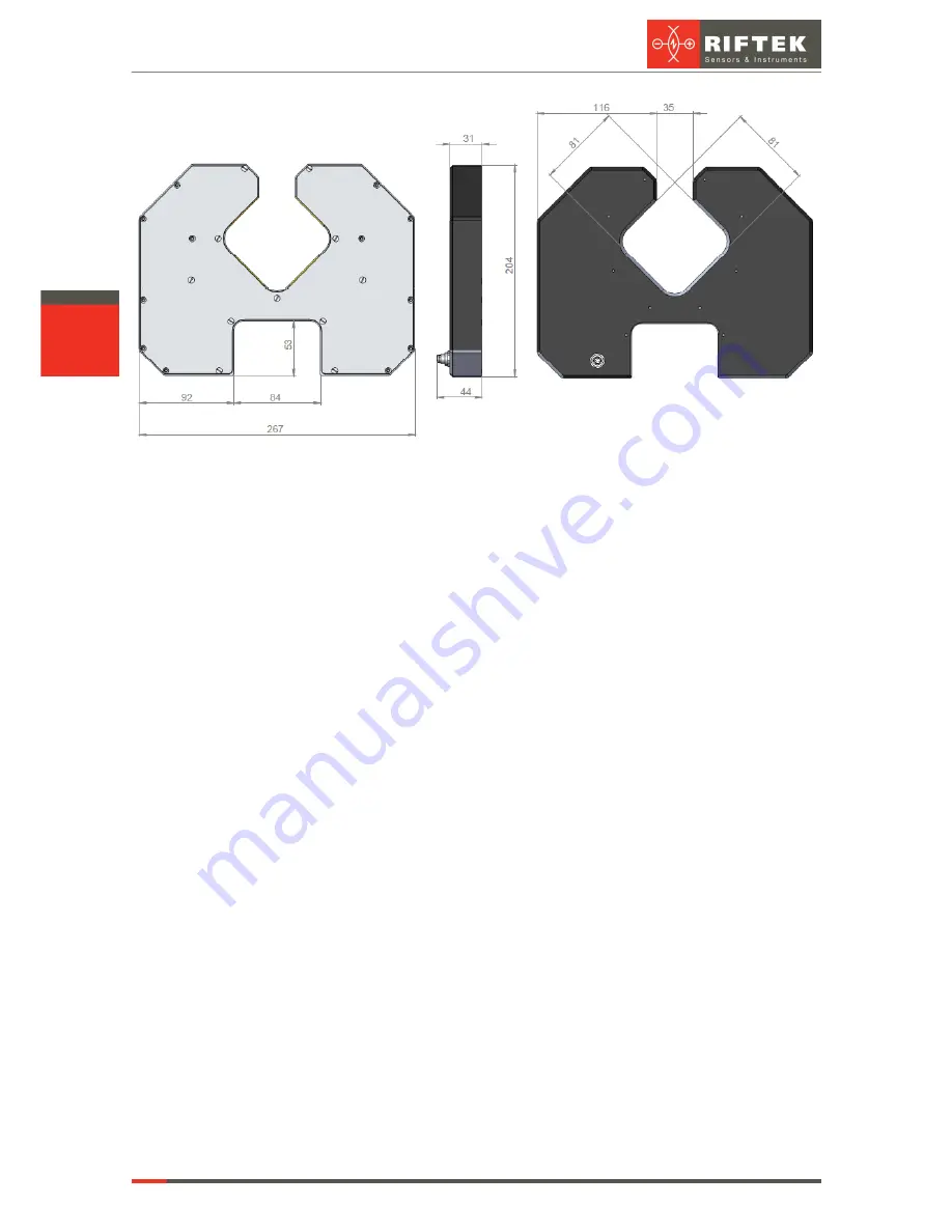
An optical micrometer (5) is installed on the carriage (3). The end sensors (not
shown) are used to monitor the end positions of the micrometer. A table with two Morse
tapers (6 and 7) is used to install the controlled shaft. The Morse tapers are mounted on a
bar (8) located along the the linear guide. One of the end sensors is mounted on the upper
taper, the latter can be reinstalled along the bar (8) in order to control the shafts of different
lengths.
In addition, the machine has a caliber, which is a part of the upper Morse taper. The
caliber is designed for an automatic re-calibration of the micrometer to eliminate the
measurement error caused by a change in the temperature of the machine.
The machine contains a mini-computer (9) with a graphic touch screen. The mini-
computer has the special software designed to control the machine and to display results.
The mini-computer can be built into the machine (as shown in Figure 3), or it can be
installed on the special stand (see Figure 4).
The back side of the machine has a power supply 220/24V (10) with a circuit
breaker (11), connector for the foot switch (12), USB connector (13) for the USB drive (for
example, for data transfer), and the Ethernet connector (14), for example, to connect to the
PC.


