

15
INSTALLATION
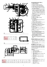
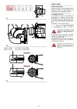
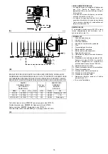
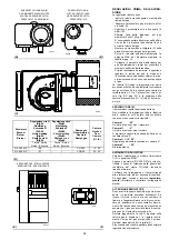
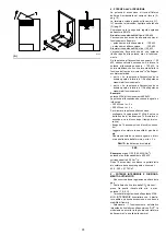
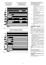
KESSELPLATTE (A)
Die Abdeckplatte der Brennkammer wie in (A)
gezeigt vorbohren. Die Position der Gewinde-
bohrungen kann mit der zur Grundausstattung
gehörenden Wärmeschild ermittelt werden.
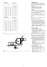
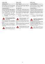
FLAMMKOPFLÄNGE (B)
Die Länge des Flammkopfs wird entsprechend
der Angaben des Kesselherstellers gewählt und
der Bereich, in dem keine Verbrennung erfolgt,
muß in jedem Fall größer als die Stärke der
Kesseltür einschließlich feuerfestes Material
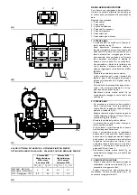
sein. Die verfügbaren Längen, L (mm), sind:
Die Brenner dürfen nicht für Kes-
sel mit Flammenumkehrung ein-
gesetzt werden.
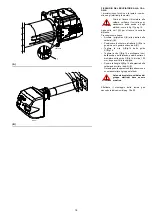
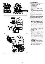
Es ist möglich, einen Schutz aus feuerfestem
Material zwischen dem Flammkopf 6)(B) und
dem feuerfesten Element des Kessels 8)(B) ein-
zufügen.
Dieser Schutz muss das Herausziehen des
Flammrohrs ermöglichen und darf die Druckent-
nahmestelle zur Steuerung der Gasarmatur
nicht behindern.
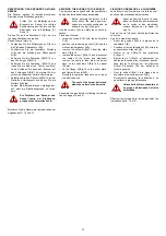
Fügen Sie den Schutz nicht an der
Elektrodengruppe ein, da er ihre
gute Funktionstüchtigkeit behindert.
L
Bereich, in dem
keine Verbren-
nung erfolgt
RX 350 S/P RX 500 S/P
180
180
ACHTUNG
ACHTUNG
INSTALLATION
BOILER PLATE (A)
Drill the combustion chamber locking plate as
shown in (A). The position of the threaded holes
can be marked using the thermal screen sup-
plied with the burner.
HEAD LENGTH (B)
The length of the combustion head must be
selected according to the instructions provided
by the manufacturer of the boiler and, in any
case, the non-combustion zone must be greater
than the thickness of the boiler door complete
with its fettling. The range of lengths available, L
(mm), is as follows:
The burners cannot be used on
flame inversion boilers.
It is possible to insert a protection
made of refractory material between the com-
bustion head 6)(B) and the boiler refractory
8)(B).
This protection must allow the blast tube to be
taken out, and must not obstruct the pressure
test point commanding the gas train.
Do not insert the protection in line
with the electrode unit, as this
would compromise its good opera-
tion.
L
Non combus-
tion zone
RX 350 S/P RX 500 S/P
180
180
WARNING
WARNING
INSTALLATION
PLAQUE CHAUDIÈRE (A)
Percer la plaque de fermeture de la chambre de
combustion comme sur la fig. (A). La position
des trous filetés peut être tracée en utilisant
l’écran thermique fourni avec le brûleur.
LONGUEUR TETE (B)
La longueur de la tête de combustion doit être
choisie selon les indications du constructeur de
la chaudière, et tout cas, la zone de non com-
bustion ne doit toutefois pas être supérieure à
l’épaisseur de la porte de la chaudière, matériau
réfractaire compris. Les longueurs, L (mm), dis-
ponible sont:
Les brûleurs ne peuvent pas être
utilisés sur des chaudières avec
inversion de flamme.
Il est possible d'insérer une protection en maté-
riau réfractaire entre la tête de combustion 6)(B)
et le réfractaire de la chaudière 8)(B).
Cette protection doit permettre l'extraction de la
buse et ne pas obstruer la prise de pression de
la commande de la rampe gaz.
Ne pas insérer la protection sur le
groupe d'électrodes car celle-ci
affecterait son bon fonctionnement.
L
Zone de non
combustion
RX 350 S/P RX 500 S/P
180
180
ATTENTION
ATTENTION
Summary of Contents for RX 350 S/P
Page 2: ......
Page 49: ...43 0 1 2 3 3 3 4 3 5 3 3 3 3 3 3 3 3 3 3 4 3 RX 350 S P...
Page 50: ...44 0 1 1 1 2 1 3 1 1 1 1 1 1 1 1 1 1 2 1 445 RX 500 S P...
Page 53: ...47 0 0 0 1 0 2 0 0 0 0 0 0 0 0 0 0 1 0 RX 350 S P...
Page 54: ...48 0 0 0 1 0 2 0 0 0 0 0 0 0 0 0 0 1 0 RX 500 S P...
Page 55: ...49 0 0 1 2 3 45 6 6 67 8 8 0 8 8 9 8 6 6 6 6 6 6 6...
Page 61: ......
Page 62: ......
Page 63: ......


