


23
20040563
GB
Installation
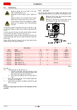
5.9.2
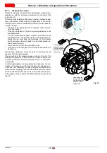
Gas feeding line
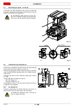
Key (Fig. 20)
1
Gas input pipe
2
Manual valve
3
Vibration damping joint
4
Pressure gauge with pushbutton cock
5
Multibloc, including:
- filter (replaceable)
- working valve
- pressure adjuster
6
minimum gas pressure switch
7
Valve leak detection control device. In compliance with the
EN 676 standard, gas valve leak detection control devices
are compulsory for burners with maximum outputs over 1200
kW.
8
Gasket
9
Gas adjustment butterfly valve
10 Maximum gas pressure switch (accessory)
11 Gas train/burner adaptor
P1 Pressure at combustion head
P2 Upstream pressure of valves/adjuster
P3 Upstream pressure of the filter
L
Gas train supplied separately with the code indicated in Tab. J.
L1 The responsibility of the installer
L1
L
P2
P1
1
2
3
4
5
6
7
8
9
10
11
D3791
Fig. 20
WARNING
Make sure that the gas train is properly installed
by checking for any fuel leaks along the fuel sup-
ply line.
Summary of Contents for RS 55/E BLU
Page 2: ...Translation of the original instructions Traducci n de las instrucciones originales...
Page 40: ......
Page 78: ...20040563 38 Appendix Ap ndice...
Page 79: ...39 20040563 Appendix Ap ndice...
Page 80: ...20040563 40 Appendix Ap ndice...
Page 81: ...41 20040563 Appendix Ap ndice...
Page 82: ...20040563 42 Appendix Ap ndice...


