background image

19 

20040563

GB

Installation

5.5.2

Boring the boiler plate

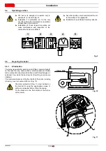
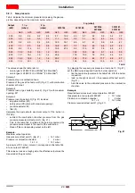
Pierce the closing plate of the combustion chamber, as in Fig. 12. 

The position of the threaded holes can be marked using the ther-
mal insulation screen supplied with the burner.

Tab. I

5.5.3

Blast tube length

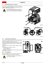
The length of the blast tube must be selected according to the in-
dications provided by the manufacturer of the boiler, and in any
case it must be greater than the thickness of the boiler door com-
plete with its refractory.

The range of lengths available, L (mm), is as follows:

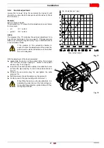
For boilers with front flue passes 13)(Fig. 13), a protection in re-
fractory material 11) must be inserted between the boiler refractory
12) and the blast tube 10). This protection must not compromise
the extraction of the blast tube.

For boilers with a water-cooled frontal, a refractory lining is not
necessary 11)-12) unless expressly requested by the boiler man-
ufacturer.

5.6

Securing the burner to the boiler

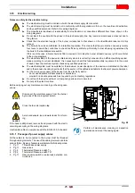
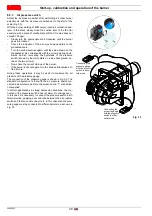
Separate the combustion head from the rest of the burner, 
(Fig. 13). To do this, proceed as follows:

loosen the screw 3) and remove the hood 1);

remove screws 2) from the two slide bars 5);

disconnect the plug 14), unscrew the cable grommet 15);

remove the screw 4);

pull back the burner on the slide bars 5) by about 100 mm;

disconnect the wires from the probe and the electrode and
then pull the burner completely off the slide bars, after
removing the split pin from the slide bar 5).

Fix the flange 9) to the plate of the boiler interposing the
insulating gasket 8) supplied. 

Use the 4 screws supplied, with a tightening torque of 35-40
Nm, after protecting their thread with anti-seize products.

mm

A

B

C

RS 55/E BLU

185

275 - 325

M12

 Fig. 12

D455

Blast tube 10)

short

255

long

390

Provide an adequate lifting system of the burner.

WARNING

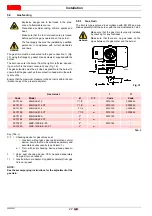
Before securing the burner to the boiler, check
(through the opening of the blast tube) that the
probe and electrode are correctly positioned, as in
Fig. 15.

WARNING

The seal between burner and boiler must be air-
tight: after the start-up, check there is no leak-
age of flue gases into the external environment.

Carry out all installation operations and mount the
casing again.

14

2

15

12

11

10

8

9

5

13

13

4

3

1

10

m

m

 Fig. 13

D8149

Summary of Contents for RS 55/E BLU

Page 1: ...n uso y mantenimiento Forced draught gas burners Quemadores de gas con aire soplado Progressive two stage or modulating operation Funcionamiento a dos llamas progresivo o modulante CODE C DIGO MODEL M...

Page 2: ...Translation of the original instructions Traducci n de las instrucciones originales...

Page 3: ...uipment 13 4 12 Control box for air fuel ratio REC27 100A2 14 4 13 Servomotor SQM33 16 5 Installation 17 5 1 Notes on safety for the installation 17 5 2 Handling 17 5 3 Preliminary checks 17 5 4 Opera...

Page 4: ...witch 29 6 5 2 Minimum gas pressure switch 29 6 5 3 Air pressure switch 30 6 6 Operation sequence of the burner 31 6 7 Final checks with burner operating 32 7 Maintenance 33 7 1 Notes on safety for th...

Page 5: ...mbodegem Tel 053 769 030 Fax 053 789 440 e mail info riello be URL www riello be This document certifies that the series of devices specified below is in compliance with the model described in the EC...

Page 6: ...risks CAUTION This symbol indicates operations which if not car ried out correctly may cause damage to the ma chine and or injury to people DANGER DANGER LIVE COMPONENTS This symbol indicates operatio...

Page 7: ...of damage to things or injury to people if such damage injury was due to any of the following causes incorrect installation start up use and maintenance of the burner improper incorrect or unreasonabl...

Page 8: ...nce Only those parts envisaged by the manufacturer can be replaced 3 2 Personnel training The user is the person body or company that has acquired the machine and intends to use it for the specific pu...

Page 9: ...ry 24h Continuous operation 1 stop every 72h Electrical supply of the system 3 400 50 3 230 50 Voltage of auxiliaries 230 50 60 110 50 60 R S 55 E TC Emission Class 1 EN267 EN676 MY Class 1 EN267 Clas...

Page 10: ...ment accuracy 1 5 dB in the manufacturer s combustion lab with burner operating on test boiler at maximum output Gas category Destination country I2E LU PL I2E R BE I2ELL DE I2Er FR I2H AT BG CH CZ DK...

Page 11: ...n motor rpm V kW A 2810 230 400 1 1 4 7 2 7 Ignition transformer V1 V2 I1 I2 220 240 V 1 x 15 kV 1 A 25 mA Absorbed electrical power kW max 1 5 Protection level IP40 Model RS 55 E BLU Electrical suppl...

Page 12: ...air at a higher temperature and or higher altitudes The heating of the air and the increase in altitude produce the same effect the expansion of the air volume i e the reduction of its density The de...

Page 13: ...e Qe kg h mbar Qe A H1 H2 H3 D388 Fig 3 kW Altitude Average barometric pressure F Air temperature C m above sea level mbar 0 5 10 15 20 25 30 40 0 100 200 300 400 500 600 700 800 900 1000 1200 1400 16...

Page 14: ...the burner must be combined with a boiler that has not been EC approved and or its combustion chamber dimensions are clearly smaller than those indicated in the diagram Fig 4 consult the manufacturer...

Page 15: ...Slide bars for opening the burner and inspecting the com bustion head 20 Gas pressure test point and head fixing screw 21 Air pressure socket 22 Flame sensor probe 23 Air damper 24 Fan air inlet 25 S...

Page 16: ...d avoid conditions that can favour the development of conden sate and humidity Otherwise before switching on again make sure that the entire control box is perfectly dry Static charges must be avoided...

Page 17: ...t fuse internal 6 3 AT DIN EN 60 127 2 5 Main power supply input current based on the operating status of the control box Undervoltage Safety stop from the operating position to the mains voltage Rest...

Page 18: ...ed as follows 1 Assemble and fix the servomotor 2 Connect the drive shaft of the servomotor by means of a lug Installation notes Arrange the H V ignition cables separately as far as possi ble from the...

Page 19: ...the boiler must be free from hazardous mixes e g chloride fluoride halo gen if present it is highly recommended to carry out cleaning and maintenance more frequently WARNING The handling operations fo...

Page 20: ...gned to operate only in positions 1 2 3 and 4 Fig 9 Installation 1 is preferable as it is the only one that allows the maintenance operations as described in this manual Installations 2 3 and 4 permit...

Page 21: ...e burner Fig 13 To do this proceed as follows loosen the screw 3 and remove the hood 1 remove screws 2 from the two slide bars 5 disconnect the plug 14 unscrew the cable grommet 15 remove the screw 4...

Page 22: ...of the burner Therefore this value must be set before adjusting the combus tion head Two adjustments of the head are foreseen the air R1 A Fig 16 the gas air R2 B Fig 16 In the diagram of Fig 17 find...

Page 23: ...coupling 4 burner in the position shown in Fig 13 on page 19 Insert the probe and electrode cables then slide the burner as far as the pipe coupling burner in the position shown in Fig 18 Connect the...

Page 24: ...ready assem bled 7 Valve seal checking device VPS Supplied separately from gas train on request 11 Gas train burner adaptor Supplied separately from gas train on request NOTE See the accompanying inst...

Page 25: ...control devices are compulsory for burners with maximum outputs over 1200 kW 8 Gasket 9 Gas adjustment butterfly valve 10 Maximum gas pressure switch accessory 11 Gas train burner adaptor P1 Pressure...

Page 26: ...lumn 1 corresponds in the table Tab K to an output of 600 kW This value serves as a rough guide the effective output must be measured at the gas meter To calculate the required gas pressure at test po...

Page 27: ...ntification label and in this manual The burners have been calibrated for intermittent operation This means that they must stop once every twenty four hours to permit the control box to check its effi...

Page 28: ...supply is 400 V To reset in case of an intervention of the thermal relay press button 1 Fig 23 5 12 Measuring the ionisation current The burner is fitted with an ionisation system to check that a flam...

Page 29: ...harac teristics label Connect two lamps or testers to the two gas line solenoids to check the exact moment in which voltage is supplied This operation is unnecessary if each of the two solenoids is eq...

Page 30: ...he burner will fire and then go into lock out after the safety time has elapsed Perform 10 ignitions with consecutive lockouts Read the quantity of gas burned on the meter This quantity must be equal...

Page 31: ...ockwise by 2 mbar and repeat the start up of the burner If the burner locks out again turn the knob clockwise again by 1 mbar 6 5 2 Minimum gas pressure switch Adjust the minimum gas pressure switch a...

Page 32: ...ground be tween the two arrows Now check the correct start up of the burner If the burner locks out again turn the knob anticlockwise a lit tle bit more During these operations it may be useful to mea...

Page 33: ...Thermostat pressure switch OUTPUT SIGNALS Thermostat pressure switch Ionisation probe ION Air pressure switch PA Minimum gas pressure switch PGmin Maximum gas pressure switch PGM Gas pressure switch...

Page 34: ...mum end of scale position Turn the air pressure switch to the maximum end of scale position The burner must stop in lockout Turn off the burner and cut off the voltage Disconnect the minimum gas press...

Page 35: ...fan or on its blades as this condition will cause a reduction in the air flow rate and provoke polluting combustion Boiler Clean the boiler as indicated in its accompanying instructions in order to m...

Page 36: ...rt 7 after having removed the screw 8 7 4 Closing the burner Remove the split pin 9 and push the burner until it is approx 100 mm from the pipe coupling Reconnect the cables and slide in the burner un...

Page 37: ...REC27 100A2 supplied When the burner starts up again the red LED goes out and the control box is reset 8 Faults Probable causes Solutions WARNING In the event of a burner lockout more than two consecu...

Page 38: ...essure Valve Proving Continuous purging kit Software interface kit ACS410 OCI410 30 Service Level Modbus interface kit OCI412 Soundproofing box kit Gas trains in compliance with EN 676 Please refer to...

Page 39: ...out Index of layouts 2 Indication of references 3 Functional layout REC27 4 Functional layout REC27 5 Functional layout REC27 6 Electrical wiring that the installer is responsible for 7 Electrical wir...

Page 40: ......

Page 41: ...de la relaci n aire combustible REC27 100A2 14 4 13 Servomotor SQM33 16 5 Instalaci n 17 5 1 Notas sobre la seguridad para la instalaci n 17 5 2 Traslado 17 5 3 Controles preliminares 17 5 4 Posici n...

Page 42: ...esostato gas de m nima 29 6 5 3 Presostato aire 30 6 6 Secuencia de funcionamiento del quemador 31 6 7 Controles finales con el quemador funcionando 32 7 Mantenimiento 33 7 1 Notas sobre la seguridad...

Page 43: ...degem Tel 053 769 030 Fax 053 789 440 e mail info riello be URL www riello be Con la presente se certifica que la serie especificada a continuaci n es conforme al modelo tipo descrito en la declaraci...

Page 44: ...e s mbolo distingue a las operaciones que si no se ejecutan correctamente podr an causar da os a la m quina y o a las personas PELIGRO PELIGRO COMPONENTES CON TENSI N Este s mbolo distinguir las opera...

Page 45: ...ucar n en caso de da os a personas y o cosas cuando los da os hayan sido originados por una o m s de las siguientes causas instalaci n puesta en funcionamiento uso y mantenimiento del quemador incorre...

Page 46: ...sustituirse 3 2 Adiestramiento del personal El usuario es la persona entidad o empresa que compra la m quina y cuya intenci n es usarla con el fin para el cual fue conce bida Suya es la responsabilid...

Page 47: ...24 h Funcionamiento continuo 1 stop cada 72 h Alimentaci n el ctrica del sistema 3 400 50 3 230 50 Tensi n auxiliares 230 50 60 110 50 60 R S 55 E TC Emisi n Clase 1 EN267 EN676 MY Clase 1 EN267 Clase...

Page 48: ...B en el laboratorio de combusti n del fabricante con quemador funcionando en caldera de prueba a la m xima potencia Categor a gas Pa s de destino I2E LU PL I2E R BE I2ELL DE I2Er FR I2H AT BG CH CZ DK...

Page 49: ...0 230 400 1 1 4 7 2 7 Transformador de encendido V1 V2 I1 I2 220 240 V 1 x 15 kV 1 A 25 mA Potencia el ctrica absorbida kW m x 1 5 Grado de protecci n IP40 Modelo RS 55 E BLU Alimentaci n el ctrica V...

Page 50: ...ionar con aire combu rente a una temperatura superior y o altitudes mayores El calentamiento del aire y el aumento de la altitud producen el mismo efecto la expansi n del volumen de aire o sea que su...

Page 51: ...zal de combusti n se debe regular en fun ci n de la potencia equivalente Qe Qe kg h mbar Qe A H1 H2 H3 D388 Fig 3 kW Altitud Presi n barom trica media F Temperatura aire C m s n m mbar 0 5 10 15 20 25...

Page 52: ...rario el quemador debe instalarse en una caldera no homologada CE y o con dimensiones de c mara de combus ti n decididamente m s peque as que las indicadas en el gr fico Fig 4 se deben consultar con l...

Page 53: ...ador e inspecci n del cabezal de combusti n 20 Toma de presi n de gas y tornillo fijaci n cabezal 21 Toma de presi n de aire 22 Sonda para controlar la presencia de llama 23 Registro de aire 24 Entrad...

Page 54: ...ontrario antes de volver a encender controlar que la caja de control est com pleta y perfectamente seca Evitar la acumulaci n de cargas electrost ticas que al con tacto pueden da ar los componentes el...

Page 55: ...5 Alimentaci n principal corriente de entrada seg n el estado de funcionamiento de la caja de control Baja tensi n Parada de seguridad desde la posici n de funcionamiento con tensi n de red Rearranque...

Page 56: ...1 Montar y fijar el servomotor 2 Conectar el cig e al del servomotor mediante un perno de enganche Notas de instalaci n Colocar los cables de encendido de alta tensi n a la mayor distancia posible de...

Page 57: ...e estar libre de mezclas peligrosas ej cloruro fluo ruro al geno si las hay se recomienda efectuar aun m s frecuentemente frecuentemente la lim pieza y el mantenimiento ATENCI N Las operaciones de tra...

Page 58: ...posiciones 1 2 3 e 4 Fig 9 Es conveniente escoger la instalaci n 1 puesto que es la nica que permite el mantenimiento tal como descrito a continuaci n en este manual Las instalaciones 2 3 y 4 permiten...

Page 59: ...to proceder de la siguiente manera aflojar el tornillo 3 y sacar la tapa 1 desenroscar los tornillos 2 de las dos gu as 5 desconectar el conector macho 14 y desenroscar el anillo pasacable 15 quitar e...

Page 60: ...desarrollar el quemador Por tanto antes de efectuar esta regulaci n se debe conocer este valor En el cabezal se deben efectuar dos regulaciones la del aire R1 A Fig 16 la del gas aire R2 B Fig 16 Enco...

Page 61: ...13 en la p g 19 Introducir el cable de la sonda y el cable del electrodo y des lizar el quemador hasta el manguito hasta que alcance la posici n indicada en la Fig 18 Conectar el conector macho del se...

Page 62: ...trol estanqueidad v lvulas VPS Se suministra aparte de la rampa de gas sobre demanda 11 Adaptador rampa quemador Se suministra aparte de la rampa de gas sobre demanda NOTA Para la regulaci n de la ram...

Page 63: ...obli gatorio para quemadores con potencia m xima superior a 1200 kW 8 Junta 9 V lvula de mariposa de gas 10 Presostato gas de m xima accesorio 11 Adaptador rampa quemador P1 Presi n en el cabezal de c...

Page 64: ...A la presi n de 12 1 mbar columna 1 corresponde en la Tab K una potencia de 600 kW Este valor sirve como primera aproximaci n el real se determi nar a trav s del contador En cambio para conocer la pr...

Page 65: ...te lo que significa que deben detenerse obligatoriamente por lo menos 1 vez cada 24 horas para permitir que la caja de control verifique su propia efi ciencia en el arranque Normalmente la parada del...

Page 66: ...ear en caso de intervenir el rel t rmico pre sionar el pulsador 1 Fig 23 5 12 Medici n de la corriente de ionizaci n El quemador est dotado de un sistema de ionizaci n para con trolar la presencia de...

Page 67: ...paralelo a las dos electrov lvulas de gas dos l mparas o un tester para controlar el momento de la lle gada de tensi n Esta operaci n no es necesaria si cada una de las electrov lvulas va equipada de...

Page 68: ...conector macho hembra 6 Fig 5 en la p g 13 del cable de la sonda de ionizaci n el quemador se enciende y se bloquea despu s de un tiempo de seguri dad Efectuar 10 encendidos con bloqueos consecutivos...

Page 69: ...ue del quemador Si el quemador se para de nuevo gire el bot n en el sentido de las agujas del reloj 1 mbar 6 5 2 Presostato gas de m nima Regular el presostato gas de m nima despu s de haber efectua d...

Page 70: ...as la hist resis del presostato representada por el campo blanco sobre fondo azul comprendido entre las dos flechas Ahora verificar si el quemador arranca correctamente Si el quemador se bloquea de n...

Page 71: ...sostato SE ALES DE SALIDA Termostato presostato Sonda de ionizaci n ION Presostato aire PA Presostato gas de m nima PGmin Presostato gas de m xima PGM Presostato gas para control de estanqueidad PGVP...

Page 72: ...asta la posici n de final de escala m nimo Girar el bot n del presostato aire hasta la posici n de final de escala m ximo El quemador debe bloquearse Apagar el quemador y cortar la tensi n Desconectar...

Page 73: ...as de la turbina reduce el caudal de aire pro vocando una combusti n defectuosa Caldera Limpiar la caldera de acuerdo con las instrucciones que la acom pa an con el fin de poder mantener intactas las...

Page 74: ...7 4 Cierre del quemador Quitar el pasador 9 y empujar el quemador hasta que est a unos 100 mm del manguito Volver a conectar los cables y desplazar el quemador hasta que haga tope Conectar el conecto...

Page 75: ...100A2 sumi nistrado En cuanto el quemador vuelve a ponerse en marcha la luz roja se apaga y la caja de control est desbloqueada 8 Anomal as Causas Soluciones ATENCI N En caso de parada del quemador pa...

Page 76: ...e Proving Kit Ventilaci n Continua Kit interfaz software ACS410 OCI410 30 Nivel Service Kit interfaz Modbus OCI412 Kit caja silenciador Rampas de gas seg n norma EN 676 Consultar el manual A Ap ndice...

Page 77: ...el ctrico ndice esquemas 2 Indicaci n referencias 3 Esquema funcional REC27 4 Esquema funcional REC27 5 Esquema funcional REC27 6 Conexiones el ctricas a cargo del instalador 7 Conexiones el ctricas K...

Page 78: ...20040563 38 Appendix Ap ndice...

Page 79: ...39 20040563 Appendix Ap ndice...

Page 80: ...20040563 40 Appendix Ap ndice...

Page 81: ...41 20040563 Appendix Ap ndice...

Page 82: ...20040563 42 Appendix Ap ndice...

Page 83: ...Fan motor PA Air pressure switch Leyenda esquemas el ctricos A1 Caja de control de la relaci n aire combustible A2 Panel Operador B Filtro antiinterferencias radio BB Componentes de los quemadores BC...

Page 84: ...Subject to modifications Con la posibilidad de modificaci n RIELLO S p A I 37045 Legnago VR Tel 39 0442 630111 http www riello it http www rielloburners com...

Reviews: