


51
20068118
GB
Maintenance
7.2.3
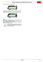
Measuring the ionisation current
The burner is fitted with an ionisation system to check that a flame
is present.
The minimum current for control box operation is 4
μ
A. The Op-
erator Panel visualises “30%” (see
parameter no. 954).
The burner provides a much higher current, so controls are not
normally required.
However, if it is necessary to measure the ionisation current, dis-
connect the plug-socket on the ionisation probe cable and insert
a direct current microammeter with a base scale of 100
μ
A - see
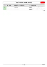
7.2.4
Checking the air and gas pressure on the
combustion head
To carry out this operation a pressure gauge must be used to
mesure the air and gas pressure at the combustion head, as
shown in Fig. 39.
WARNING
Carefully check the polarities!
D8090
Fig. 38
D8089
Checking
air pressure
Checking
gas pressure
Fig. 39
Summary of Contents for RS 25/E BLU Series
Page 2: ...Translation of the original instructions...
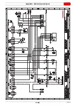
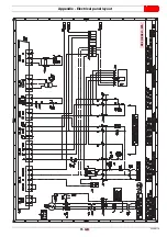
Page 65: ...63 20068118 GB Appendix Electrical panel layout RS 25 E BLU...
Page 66: ...20068118 64 GB Appendix Electrical panel layout RS 35 E BLU...
Page 67: ...65 20068118 GB Appendix Electrical panel layout RS 35 E BLU 3Ph...
Page 68: ...20068118 66 GB Appendix Electrical panel layout RS 25 35 E BLU...
Page 69: ...67 20068118 GB Appendix Electrical panel layout RS 35 E BLU 3Ph...
Page 70: ...20068118 68 GB Appendix Electrical panel layout...
Page 71: ...69 20068118 GB Appendix Electrical panel layout...
Page 72: ...20068118 70 GB Appendix Electrical panel layout...
Page 73: ...71 20068118 GB Appendix Electrical panel layout...
Page 75: ......


