


20068118
30
GB
Installation
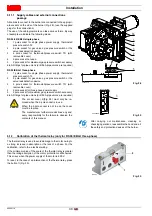
5.11.1 Supply cables and external connections
passage
All cables to connect to the burner are connected to the appropri-
ate sockets on the side of the burner (Fig. 28), (use the supplied
plugs for the connections).
The use of the cable grommets can take various forms. By way
of example we indicate the following mode:
RS 25-35/E BLU single phase
1
7 pole socket for single phase power supply, thermostat/
pressure switch TL
2
6 pole socket for gas valves, gas pressure switch or the
valve leak detection device
3
4 pole socket for thermostat/pressure switch TR (with
removable cover)
4
5 pole socket not used
5
2 pole socket for maximum gas pressure switch accessory
6-6A Fittings for pipe unions (drill if 6A pipe unions are required)
RS 35/E BLU three-phase
1
7 pole socket for single phase power supply, thermostat/
pressure switch TL
2
6 pole socket for gas valves, gas pressure switch or the
valve leak detection device
3
4 pole socket for thermostat/pressure switch TR (with
removable cover)
4
5 pole socket for three-phase power supply
5
2 pole socket for maximum gas pressure switch accessory
6-6A Fittings for pipe unions (drill if 6A pipe unions are required)
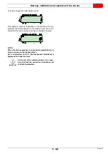
5.12
Calibration of the thermal relay (only for RS 35/E BLU three-phase)
The thermal relay is used to avoid damage to the motor owing to
a strong increase in absorption or the lack of a phase. For the
calibration, refer to the electrical wiring.
If the minimum value of the scale of the thermal relay is greater
than the rating absorption of the motor, protection is still ensured.
This arises when the power supply of the motor is 400 V.
To reset, in the case of an intervention of the thermal relay, press
the button 1)(Fig. 30).
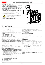
DANGER
The socket cover 3)(Fig. 29) must only be re-
moved when the 4-pole socket is in use.
When the 4-pole socket is not in use the cover
must be in place.
The manufacturer furthermore declines any and
every responsibility for the failure to observe the
contents of this manual.
After carrying out maintenance, cleaning or
checking operations, reassemble the hood and all
the safety and protection devices of the burner.
6A
5
4
3
2
1
6
Fig. 28
20052376
3
Fig. 29
20052852
Fig. 30
2
1
D8267
Summary of Contents for RS 25/E BLU Series
Page 2: ...Translation of the original instructions...
Page 65: ...63 20068118 GB Appendix Electrical panel layout RS 25 E BLU...
Page 66: ...20068118 64 GB Appendix Electrical panel layout RS 35 E BLU...
Page 67: ...65 20068118 GB Appendix Electrical panel layout RS 35 E BLU 3Ph...
Page 68: ...20068118 66 GB Appendix Electrical panel layout RS 25 35 E BLU...
Page 69: ...67 20068118 GB Appendix Electrical panel layout RS 35 E BLU 3Ph...
Page 70: ...20068118 68 GB Appendix Electrical panel layout...
Page 71: ...69 20068118 GB Appendix Electrical panel layout...
Page 72: ...20068118 70 GB Appendix Electrical panel layout...
Page 73: ...71 20068118 GB Appendix Electrical panel layout...
Page 75: ......


