


35
20068118
GB
Start-up, calibration and operation of the burner
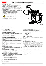
6.6.1.5 Reset procedure
The burner is in lockout when the red indicator light on the oper-
ator panel is lit up, and the display visualises the lockout code (in
the example alongside
c: 4
) and the relative diagnostics (in the
example
d: 3
) alternately.
To reset, press the
“i/reset”
key for 1s: the display will show
“rE-
SEt”
. When the key is released, the lockout signal will disappear
and the red indicator light will switch off.
The control box is reset.
6.6.1.6 Manual lockout procedure
If necessary, it is possible to manually block the control box and,
consequently, the burner, by pressing the key
“i/reset“
simulta-
neously with any other key of the operator panel.
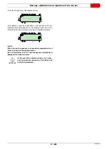
6.6.1.7 Manual operation procedure
After the adjustment of the burner and the setting of the points on
the modulation curve, it is possible to manually check the opera-
tion of the burner along the entire curve.
Example:
the burner is working at the requested load percentage: 20%.
Press the
“F”
key for 1 second: “
LoAd”
is displayed and the load
percentage flashes.
Releasing the key “
F
” the standard visualisation appears, with the
current load percentage flashing: this means that the burner is
working in Manual mode (any outside adjustment is excluded and
only the safety devices are active).
Keep the
“F”
key pressed and, with the keys “
+”
or “
–”
, increase
or decrease the load percentage.
To exit manual mode, press the keys “
+
” and “
-
” (
ESC
) simultane-
ously for 3 seconds: the burner will work in Automatic mode and
the output will depend on the thermostat/adjustment pressure
switch (TR).
6.6.2
Info mode
The
Info mode
(
InFo
) visualises general system information. To
access this level you must:
press the “
i/reset
” key for 1-3 s.
Release the key immediately when the display shows
“InFo”
.
The list of parameters (in the sequence in which they are dis-
played) is shown in Tab. L.
Tab. L
CAUTION
With the selector “
0-1
burner does not stop immediately, but the switch-
off phase is activated.
D90
0
7
P
%
s
min
V
h
D90
0
8
P
h
V
min s
%
D
9013
P
%
s
min
V
h
/reset
D
9014
P
h
V
min s
%
D901
5
P
s
min
V
h
No.
Parameter
167
Volumetric delivery of fuel in the unit of measurement
selected
162
Operation time with flame
163
Operation time
164
No. of resettable ignitions
166
Total no. of ignitions
113
Identification code of the burner
107
Software version
108
Software variation
102
Control box test date
103
Identification code of the control box
104
Identification number of the group of parameters set
105
Version of the group of parameters
143
Reserved
End
D
9016
P
s
h
V
min
D90
1
7
P
s
min
V
h
ESC
/reset
P
%
min
V
h
s
D
9019
Summary of Contents for RS 25/E BLU Series
Page 2: ...Translation of the original instructions...
Page 65: ...63 20068118 GB Appendix Electrical panel layout RS 25 E BLU...
Page 66: ...20068118 64 GB Appendix Electrical panel layout RS 35 E BLU...
Page 67: ...65 20068118 GB Appendix Electrical panel layout RS 35 E BLU 3Ph...
Page 68: ...20068118 66 GB Appendix Electrical panel layout RS 25 35 E BLU...
Page 69: ...67 20068118 GB Appendix Electrical panel layout RS 35 E BLU 3Ph...
Page 70: ...20068118 68 GB Appendix Electrical panel layout...
Page 71: ...69 20068118 GB Appendix Electrical panel layout...
Page 72: ...20068118 70 GB Appendix Electrical panel layout...
Page 73: ...71 20068118 GB Appendix Electrical panel layout...
Page 75: ......


