5
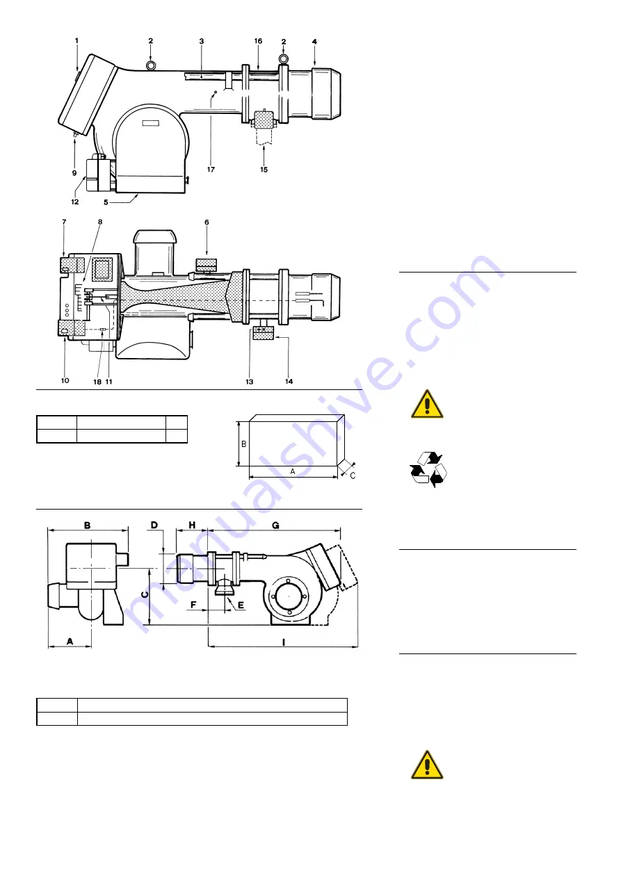
BURNER DESCRIPTION (A)
1 Flame viewer
2 Lifting rings
3 Slide bars for opening the burner and
inspecting the combustion head (see note)
4 Combustion head (two lengths)
5 Air gate valve
6 Air pressure switch
7 Motor contact-maker and thermal relay
(GAS 8-9 direct starting)
8 Terminal strip
9 Fair lead (standard equipment)
(Installer-set electrical equipment)
10 Control box with lock out pilot light and lock
out reset button
11 Combustion head drive rod
12 Air control servomotor
13 Gas pressure test point to sleeve
14 MAX gas pressure switch
15 (Gas input pipework)
16 Sleeve
17 Fan pressure test point
18 Plug-socket on ionisation probe cable
PACKAGING-WEIGHT (B)
(Approximate measurements)
•
The burners are shipped in cardboard boxes with
the maximum dimensions shown in Table (B).
The burner stands on a wooden base which
may be lifted by fork-lifts.
•
The weight of the burner complete with pack-
aging is indicated in Table (B).
Checking the consignment
MAX. DIMENSIONS (C)
(Approximate measurements)
The maximum dimensions of the burner are giv-
en in (C).
Bear in mind that inspection of the combustion
head requires the burner to be opened by with-
drawing the rear part on the slide bars.
The maximum dimensions of the burner when
open are given by measurement I.
STANDARD EQUIPMENT
•
1 Gas train flange
•
1 Flange gasket
•
8 Screws
•
1 Heat shield
•
1 Instruction booklet
•
1 Spare parts list
•
2 Extensions (only for long head version)
After removing all the packag-
ing, check the integrity of the
contents. In the event of doubt,
do not use the burner; contact
the supplier.
The packaging elements
(wooden cage or cardboard
box, nails, clips, plastic bags,
etc.) must not be abandoned as
they are potential sources of
danger and pollution; they
should be collected and dis-
posed of in the appropriate
places.
Before opening long-headed
burner (574), fit the two exten-
sions supplied as standard
equipment with the system on
slide bars 3)(A) and support the
burner on the wheel-mounted
stand supplied as an extra unit,
fig.(G)p.4, or other suitable
means.
(A)
(B)
mm
A
B
C
kg
GAS 9/2
2040
1130
1180
230
mm
A
B
C
D
E
F
G
H
I
L
GAS 9/2
445
330
495
295
Rp2
225
168
444-574
1627 1200
D88
D3438
D3442
(C)
D37
CAUTION
WARNING
Summary of Contents for GAS 9/2
Page 2: ......


