background image

12

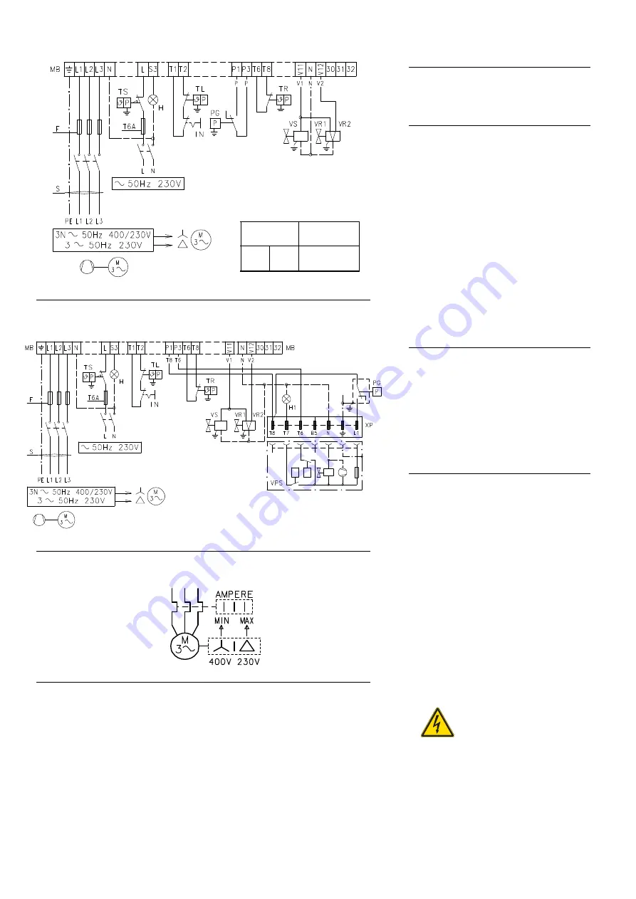
LAYOUT (A) - The GAS 9/2 Models electrical
connection three-phase power supply with-
out leak detection control device.

LAYOUT (B) - The GAS 9/2 Models electrical
connection three-phase power supply with
VPS leak detection control device.

Gas valve 8)-9)p. 10 leak detection control takes
place immediately before every burner starting.

KEY TO LAYOUTS


(A) - (B)

IN

- Manual burner stop switch

MB

- Burner terminal strip

PG

- Min. gas pressure switch

H

- Remote lock-out signal

H1

- Remote lock-out signal of leak detection

control device

TR

- High-low mode load control system:

controls operating stages 1 and 2.
If the burner is to be set up for single
stage operation, replace of remote con-
trol device TR with a jumper.

TL

- Load limit remote control system:

shuts down the burner when the boiler
temperature or pressure reaches the pre-
set value.

TS

- Safety load control system:

operates when TL is faulty

VR1 - Gas valve, stage 1
VR2 - Gas valve, stage 2
VS

- Safety valve

XP

- Plug for leak detection control device

LAYOUT (C)
Calibration of thermal cut-out 7)(A) p. 5

This is required to avoid motor burn-out in the
event of a significant increase in power absorp-
tion caused by a missing phase.
- If the motor is star-powered, 

400 V

, the cursor

should be positioned to "MIN". 

- If the motor is delta-powered, 

230 V

, the cursor

should be positioned to "MAX".

Even if the scale of the thermal cut-out does not
include rated motor absorption at 400 V, protec-
tion is still ensured in any case.

N.B.

• Models GAS 9/2 three-phase leave the factory

preset for 400 V power supply. If 230 V power
supply is used, change the motor connection
from star to delta and change the setting of the
thermal cut-out as well.

• The GAS 9/2 burners have been type- ap-

proved for intermittent operation. This means
they should compulsorily be stopped at least
once every 24 hours to enable the control box
to check its own efficiency at start-up. Burner
halts are normally provided for automatically by
the boiler load control system.
If this is not the case, a time switch should be
fitted in series to IN to provide for burner shut-
down at least once every 24 hours.

• The GAS 9/2 burner is factory set for two-stage

operation and must therefore be connected to
control device TR. 
Alternatively, if single stage operation is re-
quired, instead of control device TR install a
jumper lead between terminals 6 and 7 of the
terminal strip.

Do not invert the neutral with
the phase wire in the electric-
ity supply line. Inverting the
wires will make the burner go
into lock-out because of fir-
ing failure.

CALIBRATION OF THERMAL RELAY

(A)

(B)

ELECTRICAL CONNECTION OF BURNER BY INSTALLER

Without leak detection control device

ELECTRICAL CONNECTION OF BURNER BY INSTALLER

With VPS leak detection control device

Cable selection 

GAS 9/2

230V

400V

F
S

A

mm

2

T 50

6

T 40

4

D2901

D2903

D867

(C)

DANGER

Summary of Contents for GAS 9/2

Page 1: ...Installation use and maintenance instructions 20014474 5 01 2018 Forced draught gas burners Two stage operation CODE MODEL TYPE 20014057 GAS 9 2 1114 T 20014058 GAS 9 2 1114 T GB...

Page 2: ......

Page 3: ...The instruction manual supplied with the burner is an integral and essential part of the product and must not be sepa rated from it it must therefore be kept carefully for any necessary consultation...

Page 4: ...expressly named by the manufacturer the type and pressure of the fuel the voltage and frequency of the elec trical power supply the minimum and maximum deliveries for which the burner has been regulat...

Page 5: ...ire and single stage on off Standard applications Boilers water steam diathermic oil Ambient temperature C 0 40 Combustion air temperature C max 60 In conformity with EEC Directives 2006 95 2004 108 2...

Page 6: ...This kit must be fitted whenever the the burner is to be operated on town gas Code is suitable for the both standard and ex tended head FLAME SENSOR KIT Code 3010359 SUPPORT D Code 3000731 The support...

Page 7: ...ts The maximum dimensions of the burner are giv en in C Bear in mind that inspection of the combustion head requires the burner to be opened by with drawing the rear part on the slide bars The maximum...

Page 8: ...ar gins of safety and therefore the entire FIRING RATE range may be used COMMERCIAL BOILERS The burner boiler combination does not pose any problems if the boiler is CE type approved and its combustio...

Page 9: ...dered Example Burner GAS 9 2 Natural gas PCI 10 kWh Nm3 curve 1 Gas pressure at test point 13 A p 5 24 mbar Pressure in combustion chamber 2 mbar 24 2 22 mbar in the GAS 9 2 graph this corresponds to...

Page 10: ...is stage slide the burner fully out from slide bars 6 Before securing the combustion head to the boiler make sure the probe and the electrode are correctly positioned as shown in C If positioning is i...

Page 11: ...or 1 to the reference position defined by the chart this moving rod and shut ter mounted inside the combustion head Positioning can be read by the index on the sector itself or on the graduated cylind...

Page 12: ...h EN 676 Standards gas valve leak detection control devices are compulsory for burners with maximum out puts of more than 1200 kW 13 Gas train burner adaptor P1 Pressure at combustion head P2 Pressure...

Page 13: ...9 A p 5 The fair leads and precut holes can be used in various ways One example is given be low GAS 9 2 1 Three phase power supply Pg 11 2 Single phase power supply Pg 7 3 Remote control device TR Pg...

Page 14: ...o MAX Even if the scale of the thermal cut out does not include rated motor absorption at 400 V protec tion is still ensured in any case N B Models GAS 9 2 three phase leave the factory preset for 400...

Page 15: ...ect position and establishes when the stage 2 gas valve will be energized It makes a maximum rotation of 90 in 5s It is equipped with 7 cams which can be adjust ed by 4 coloured levers A graduated pla...

Page 16: ...n the fol lowing sequence 1 Blue lever 2 Orange lever 3 Black lever 4 Red lever The straight line 2 A marks the lever sequence Manuel air damper section Factory is setting at 30 This damper section sh...

Page 17: ...s 3s In order to measure the firing output Disconnect the plug socket 18 A p 5 on the ionization probe cable the burner will fire and then go into lock out after the safety time has elapsed Perform 10...

Page 18: ...ention as a rule the air pressure switch must limit the CO in the fumes to less than 1 10 000 ppm To check this insert a combustion analyser into the chimney slowly close the fan suction inlet for ex...

Page 19: ...rols boiler tempera ture or pressure point C The control box will continue however to mon itor flame presence and the correct position of the air pressure switch When the temperature or the pressure i...

Page 20: ...been carried out in accordance with the burner s electrical diagrams an ignition cycle with closed gas ball valve dry test must be per formed 1 The manual ball gas valve must be closed 2 The electrica...

Page 21: ...t the burner if the combustion values found at the beginning of the operation do not comply with the regulations in force or at any rate do not correspond to good combustion Use the appropriate card t...

Page 22: ...ormer electrical connections Check 32 Control box defective Replace 33 A cock down line of the gas train is closed Open 34 Air in pipework Bleed air The burner goes to lock out right after flame appea...

Page 23: ...e signal Electrical supply lower than 170V Lock out Extraneous light Key Off Yellow Green Red SIGNAL PROBABLE CAUSE 2 flashes The flame does not stabilise at the end of the safety time faulty ionisati...

Page 24: ...RIELLO S p A I 37045 Legnago VR Tel 39 0442 630111 http www riello it http www riello com Subject to modifications...

Reviews: