Riello G5R MC Installation, Use And Maintenance Instructions Download Page 9

20013743

GB

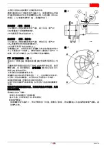
Combustion head settings indicated in the table are valid
for most cases. The setting of the fan output according to
the installation should normally be done only through the
air damper. Should one subsequently want to retouch
also the setting of the combustion head (fig. 6), with the
burner running, operate on the rod 

(1)

 with a 6 mm span-

ner 

(2)

 as follows:

Turn to the right: (sign 

+

):

In order to increase the volume of air entering the com-
bustion chamber and thus diminishing its pressure.
There is a reduction of CO

2

 and the adhesion of the

flame to the air diffuser disc improves. (

Setting advisable

for ignitions at low temperatures

).

Turn to the left: (sign 

):

In order to reduce the volume of air entering the combus-
tion chamber and thus increasing its pressure. The CO

2

improves and the adhesion of the flame to the diffuser
tends to reduce. (

This setting is not advisable for igni-

tions at low temperatures

).

In any case do not bring the combustion head setting
more than one point away from that indicated in the
schedule. One set-point corresponds to 3 turns of the
rod; a hole 

(3)

 at its end facilitates counting the number

of turns.


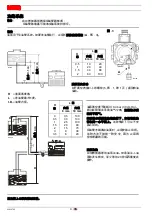
AIR DAMPER ADJUSTMENT,

 (fig. 7)

The mobile air damper 

(A)

 operated by the jack 

(B)

 as-

sures the complete opening of the air intake.
The regulation of the air-rate is made by adjusting the
fixed air damper 

(C)

, after loosing the screws 

(D)

.

When the optimal regulation is reached, 

screw tight the screws (D)

 to assure a free movement of

the mobile air damper 

(A)

.

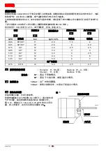
The settings indicated in the table refer to the burner with its metal cover fitted and the combustion
chamber with “zero” depression.
These regulations are purely indicative. 
Each installation however, has its own unpredictable working conditions: actual nozzle output;
positive or negative pressure in the combustion-chamber, the need of excess air, etc. 
All these conditions may require a different air-damper setting.

It is important to take account of the fact that the air output of the fan differs according to
whether the burner has its metal cover fitted or not.  

Therefore we recommended to proceed as follows:
–  adjust the air damper as indicated in the table;
–  mount the cover, simply by means of the upper screw;
–  check smoke number;
–  should it become necessary to modify the air output, remove the cover by loosening the screw,

adjust the air damper, remount the cover and finally recheck the smoke number.

1

2

3

6

D5551

D

C

D5555

D

A

B

Fig. 6

Fig. 7

4

Summary of Contents for G5R MC

Page 1: ...20013743 3 04 2011 Installation use and maintenance instructions Light oil burner CODE MODEL TYPE 20013623 G5R MC 447T1 GB CN One stage operation...

Page 2: ...safety start up use and maintenance of the burner DELIVERY OF THE SYSTEM AND THE INSTRUCTION MAN UAL When the system is delivered it is important that The instruction manual is supplied to the user b...

Page 3: ...0 185 kW It is strongly recommended a periodic check of the pump pressure operation annually or better every six months if the burner operation is continuous If the value is lower than 1 bar compared...

Page 4: ...e No 1 Screw with two nuts for flange No 1 Insulating gasket No 3 FIRING RATE OVERALL DIMENSIONS 0 8 0 0 4 Pressure in the combustion chamber mbar 2 3 4 5 Light oil output kg h 25 30 60 Thermal power...

Page 5: ...between the boiler door and the burner flange This insulating gasket has six holes which if necessary can be modified as shown on the drawing on the right D5242 Fig 2 Verify that the installed burner...

Page 6: ...leakage of the valve PRIMING THE PUMP Start the burner and wait for the priming Should lock out occur prior to the arrival of the fuel await at least 20 seconds before repeating the operation A filte...

Page 7: ...OX see fig 4 To remove the control box 1 from the burner Unscrew the fissing screws on the burner cover and remove it Unscrew the fissing screws 2 on the plate and remove the control box 1 Screw the t...

Page 8: ...uring ignitions at low temper atures PUMP PRESSURE 12 bar the pump leaves the factory set at this value 14 bar improves flame retention it is therefore suitable for ignitions at low temperatures COMBU...

Page 9: ...ting the number of turns AIR DAMPER ADJUSTMENT fig 7 The mobile air damper A operated by the jack B as sures the complete opening of the air intake The regulation of the air rate is made by adjusting...

Page 10: ...s discon nected or broken FAILURE DETECTION ON HEATING DEVICE Only for type 447T1 The plug fitted in the panel is placed in the position corre sponding to Resistance ON see fig 8 When the remote contr...

Page 11: ...ve same openings suitable for the passage of air nec essary for combustion To be sure about this you have to control the smoke number of exhaust gas with all the windows and doors closed If in the pla...

Page 12: ...tion areas and in the combustion product waste pipe Clean the filter in the oil suction line and in the pump Check for correct fuel consumption Check that the burner electrical connections are correct...

Page 13: ......

Page 14: ...20013743 CN Technical Assistance Centre Assistance Centre Maintenance Contract...

Page 15: ...C 2006 95 EC 2006 42 EC O EN 60529 IP 40 7 1 447T1 28 60 kW 2 3 5 kg h 20 C 4 6 mm2 s 1 5 E Hi 11 86 kWh kg 230V 10 50Hz 0 75A 2800 rpm 294 rad s 4 F 8 kV 16 mA 7 15 bar 0 185 kW 1 3 7 1 2 3 4 5 6 7 8...

Page 16: ...20013743 2 CN 2 1 2 4 1 2 1 3 0 8 0 0 4 mbar 2 3 4 5 kg h 25 30 60 kW D5226 35 40 45 50 55 0 2 0 6 2 3 270 122 224 130 33 4 5 80 228 11 175 D4646 180 75 72 150 4 5...

Page 17: ...3 20013743 CN 9 1 6 6 D5242 2 2 D5572 S7384...

Page 18: ...N 0 4 bar 30 cm Hg 20 H L 8 mm 10 mm 0 5 1 1 5 2 10 20 40 60 20 40 80 100 A 3 A H L 8 mm 10 mm 0 0 5 1 1 5 2 3 3 5 35 30 25 20 15 8 6 100 100 100 90 70 30 20 H 4 m H H 4 m 0 1 m D5219 D5220 D5199 H L...

Page 19: ...5 20013743 CN 1mm 4 1 2 1 2 1 2 1 D4677 A 531SE C E F FR P E H I M PE R TL TS Y 4...

Page 20: ...Steinen H Q Danfoss H 60 80 12 bar 14 bar 5 12bar 0 75 GPH 2 5 GPH bar kg h 4 0 60 60 80 11 2 3 1 5 2 0 65 60 80 12 2 6 2 2 2 0 75 60 12 3 0 2 5 2 5 0 85 60 12 3 4 3 3 1 00 60 12 4 0 4 4 5 1 10 60 12...

Page 21: ...7 20013743 CN 6 6mm 2 1 CO2 CO2 3 1 3 7 A B C D D A 0 1 2 3 6 D5551 D C D5555 D A B 6 7 4...

Page 22: ...20013743 8 CN 2 Resistance OFF 8 LED 447T1 Resistance ON 8 LED 1 LED 2 LED Resistance OFF 9 3 10 LED S7059 531SE B S7060 LED 8 9 A 2 2 5 mm 4 0 3 mm D5230 A 10...

Page 23: ...9 20013743 CN 120 D5329 120 12 12 5...

Page 24: ...20013743 10 CN CO2 CO ppm NOx ppm...

Page 25: ......

Page 26: ......

Page 27: ......

Page 28: ...I 37045 Legnago VR Tel 39 0442 630111 http www riello it http www rielloburners com Manufacturing site Riello Heating Equipment Shanghai CO LTD No 388 Jinbai Road Jinshan Industrial Zone 201506 Shang...

Reviews: