


5
20013743
GB
ELECTRICAL WIRING
ATTENTION:
Do not swap neutral and phase over, follow the diagram
shown carefully and carry out a good earth connection.
The section of the conductors must be at least 1mm².
(Unless re-
quested otherwise by local standards and legislation).
The electrical wiring carried out by the installer must be in
compliance with the rules in force in the country.
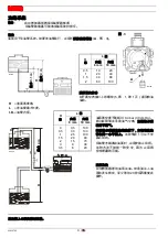
CONTROL BOX,
(see fig. 4)
To remove the control box (1) from the burner:
Unscrew the fissing screws on the burner cover and remove it.
Unscrew the fissing screws (2) on the plate and remove the
control box (1).
Screw the two fissing screws (2) and reassemble the burner
cover.
Fix the control box (1) with plate far from the burner.
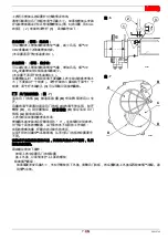
TESTING
Check the shut-down of the burner by opening the thermostats.
2
1
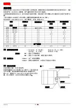
D4677
Key to lay-out
A
- Control box 531SE
C
- Capacitor
E
- Electrode
F
- Fuse
FR
- P.E. Cell
H
- Lock-out signal
I
- Main switch
M
- Motor
PE
- Burner-earth
R
- Heater
TL
- Limit thermostat
TS
- Safety thermostat
Y
- Oil valve
Fig. 4
Summary of Contents for G5R MC
Page 13: ......
Page 14: ...20013743 CN Technical Assistance Centre Assistance Centre Maintenance Contract...
Page 17: ...3 20013743 CN 9 1 6 6 D5242 2 2 D5572 S7384...
Page 19: ...5 20013743 CN 1mm 4 1 2 1 2 1 2 1 D4677 A 531SE C E F FR P E H I M PE R TL TS Y 4...
Page 21: ...7 20013743 CN 6 6mm 2 1 CO2 CO2 3 1 3 7 A B C D D A 0 1 2 3 6 D5551 D C D5555 D A B 6 7 4...
Page 23: ...9 20013743 CN 120 D5329 120 12 12 5...
Page 24: ...20013743 10 CN CO2 CO ppm NOx ppm...
Page 25: ......
Page 26: ......
Page 27: ......