


20013743
8
GB
FUEL HEATING
In order to obtain smooth starting and operation across
its output range the burner is fitted with an electric
resistance, which heats up the gas oil in the nozzle
line. This resistance is energized when the thermostat
calls for heat and after a delay of approximately two
minutes depending on room temperature, the motor
will start. The resistance remains inserted and locks-
out on the shut-down of the burner.
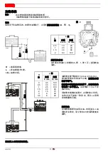
Attention
Should you want to cut off the electric resistance (on
setting the burner or when the ambient temperature
does not require it,
etc. . .),
take the plug off the panel
of the control box and plug it into the
“Resistance
OFF”
(see fig. 8). In this case the burner starts
up when the thermostats close.
NOTE
The warning light
(LED)
is
ON
but when the resist-
ance works. It is
OFF
when the resistance is discon-
nected or broken.
FAILURE DETECTION ON HEATING
DEVICE -
Only for type 447T1
The plug fitted in the panel is placed in the position corre-
sponding to
“Resistance ON”
(see fig. 8).
When the remote control closes, the
LED
lights up and,
after about two minutes, the burner starts up.
1)
If the
LED
is
OFF
, the heating resistance placed
in the nozzle-holder is off.
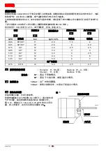
2)
If the
LED
is
ON
and nevertheless the burner does not run, place the plug in the position corre-
sponding to
“Resistance OFF”
(see fig. 9). If the motor runs, the delaying device inside
the control box is out of order.
3)
If the motor does not run, it means that the failure is neither in the panel nor in the resistance, but
elsewhere.
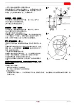
ELECTRODE SETTING,
(see fig. 10)
PLUG
Resistance ON
Resistance OFF
LED
S7059
Control box
531SE B
PLUG
Resistance OFF
S7060
LED
Fig. 8
Fig. 9
NORMAL OPERATION
BURNER DOES NOT OPERATE
IMPORTANT:
THESE DIMENSIONS MUST BE
OBSERVED
Before removing or assembling the
nozzle, loosen the screw
(A)
and
move the electrodes ahead.
2 – 2.5
mm
4
±
0.3 mm
D5230
A
Fig. 10
Summary of Contents for G5R MC
Page 13: ......
Page 14: ...20013743 CN Technical Assistance Centre Assistance Centre Maintenance Contract...
Page 17: ...3 20013743 CN 9 1 6 6 D5242 2 2 D5572 S7384...
Page 19: ...5 20013743 CN 1mm 4 1 2 1 2 1 2 1 D4677 A 531SE C E F FR P E H I M PE R TL TS Y 4...
Page 21: ...7 20013743 CN 6 6mm 2 1 CO2 CO2 3 1 3 7 A B C D D A 0 1 2 3 6 D5551 D C D5555 D A B 6 7 4...
Page 23: ...9 20013743 CN 120 D5329 120 12 12 5...
Page 24: ...20013743 10 CN CO2 CO ppm NOx ppm...
Page 25: ......
Page 26: ......
Page 27: ......