13
5
Preparation for start up
5.1
Combustion head setting
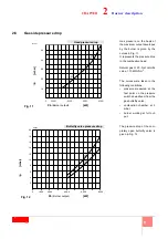
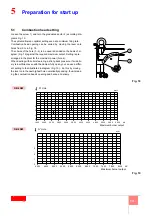
Loosen the screw 1) and turn the graduated sector 2) according dia-
grams Fig. 19.
The system allows an optimal setting even at a minimum firing rate.
Combustion head opening can be varied by moving the lever onto
holes from 0 to 6, Fig. 18.
The choice of the hole (0 - 6) to be used is decided on the basis of di-
agram (Fig. 19) against the required maximum output. Setting is pre-
arranged in the plant for the maximum power (hole 6).
When dealing with boilers featuring a strong back pressure, if air deliv-
ery is insufficient even with the damper fully open, you can use a differ-
ent setting to that illustrated in diagram (Fig. 19) - do this by moving
the lever onto the next highest hole numerically speaking, thus increas-
ing the combustion head’s opening and hence air delivery.
Fig. 18
1
2
0
1
2
3
4
5
6
D8299
1600
2000
2400
2800
3200
3600
4000
4400
kW
4800
5200
3
2
1
0
5600
6000
N° Hole
Maximum burner output
Fig. 19
N° Hole
Maximum burner output
DB 6 SM
DB 4 SM
D7905
D8417
kW
7800
8200
7400
7000
6600
6200
5800
5400
5000
4400
4000
0
1
2
3
Maximum burner output
Summary of Contents for DB 6 SM CO1 A0
Page 2: ......
Page 43: ...1...
Page 44: ...2 1 3 3 3 2 4 4 4 5 6 8 9 3 10 10 10 10 10 4 11 11 12 5 13 13 14 15 15 17 18 18 6 19 19...
Page 47: ...5 2 2 3 1 2 3 4 5 6 7 8 9 10 11 UV 12 13 14 15 16 17 18 19 20 21 M12x16 2 20076243...
Page 49: ...7 2 DN 80 160 18 4 54 5 4 9 5 3 8 0 M18 D8325 7 8 D3974 9 D7549 DB6 SM...
Page 53: ...11 4 4 1 D7543 C GF HPG LPG MM PA PGM PGm RG SRV VE VPS VR VS 0 5 4 bar 500 mbar 16...
Page 54: ...12 4 4 2 MB PA PGM SM UV UV TA TB D9854 17...
Page 56: ...14 5 5 2 20 20 20076847...
Page 57: ...15 5 5 3 1 4 2 3 5 6 7 1 2 0 3 20 4 5 20 130 1 4 5 4 130 22 21 D1500 3 2 4 1 22 1 2 3 4 D1499...
Page 58: ...16 5 MAN 3 1 130 90 2 22 2 22 20 2 2...
Page 60: ...18 5 5 7 70 A 187 V 100 A c c 100 F 1V c c 5 8 1 2 3 4 5 1 2 3 4 5 6 D1143 26...
Page 61: ...19 6 6 1 1 2 3 VR VR VS VR...
Page 62: ...20 6...
Page 63: ......

