


10
3
Installation
3.1
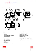
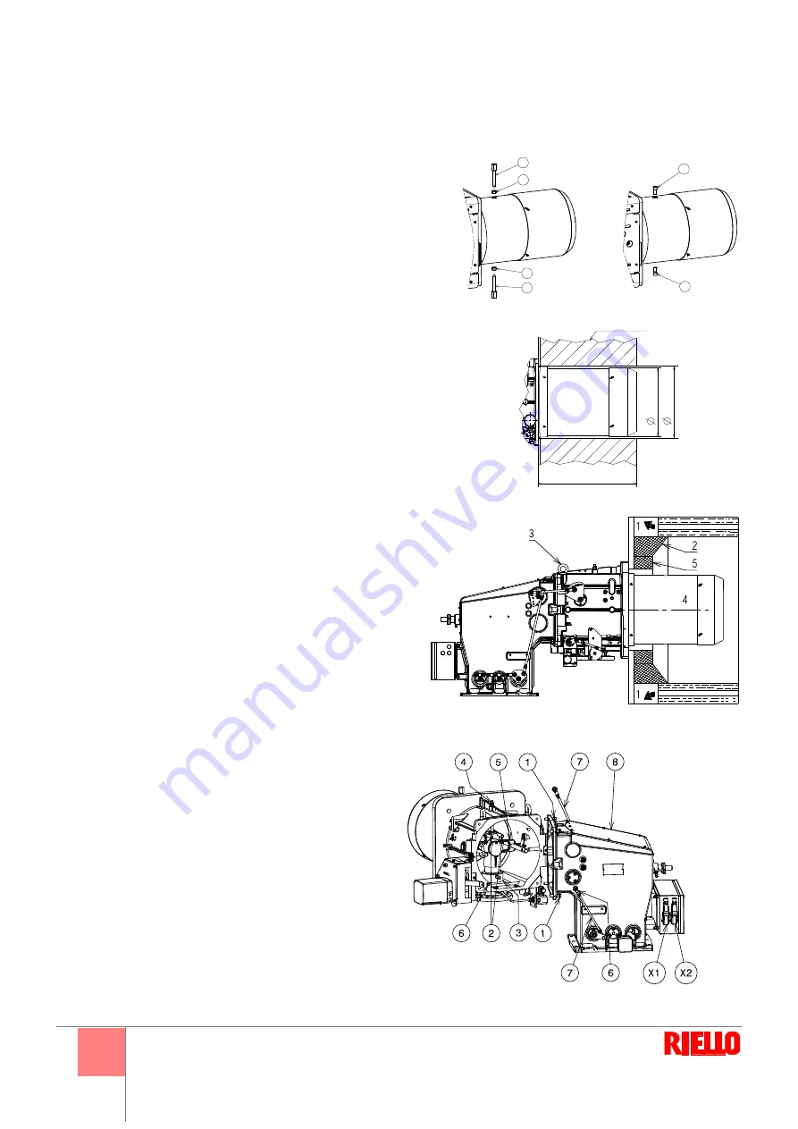
Removal of the locking screws from the
shutter
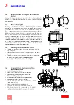
Remove the screws and the nuts 1) and 2)(Fig. 13), before installing the
burner on the boiler. Replace them with the screws 3) M12x16 supplied
with the burner.
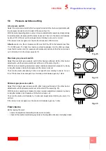
3.2
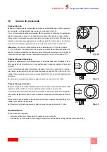
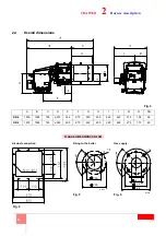
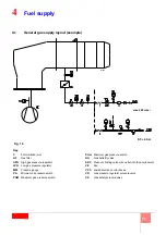
Blast tube length
The length of the blast tube must be selected according to the indications
provided by the manufacturer of the boiler, and in any case it must be
greater than the thickness of the boiler door complete with its fettling. For
boilers with front flue passes 1) or flame inversion chambers, protective
fettling in refractory material 5) must be inserted between the boiler fet-
tling 2) and end cone 4). This protective fettling must not compromise the
extraction of the blast tube. For boilers having a water-cooled front the
refractory fettling 2)-5)(Fig. 14) is not required unless it is expressly
requested by the boiler manufacturer. The figure alongside shows how to
fix the burner to a boiler without a cooled frontal. The head should not jut
out more than 200 mm. In any case, the fettled wall should not extend
beyond the end of the burner combustion head.
3.3
Securing the burner to the boiler
•
Prepare an adequate system of hoisting by hooking onto the
rings 3) Fig. 14.
•
Slip the thermal protection (standard equipment) onto the blast
tube 4).
•
Place entire burner on the boiler hole arranged previously and
fasten with the screws given as standard equipment.
The coupling of the burner-boiler must be air-tight.
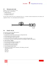
3.4
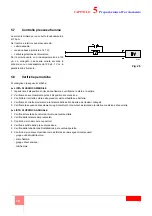
Accessibility to the interior of the
combustion head
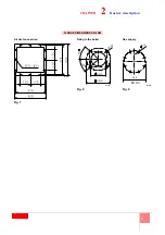
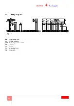
•
Switch off the electrical power.
•
Unscrew the locknut 6) and release the tie rod 7).
•
Disconnect the servomotor sockets X1 and X2.
•
Remove the 4 fixing screws 1).
•
Open burner at hinge (see Fig. 15) (only optional).
•
Disconnect the wires 2) and the electrode.
•
Turn the under part of the elbow 3) anticlockwise until it
comes free of its slot.
•
Unscrew screw 4) with pressure test point.
•
Extract the internal part 5) of the combustion head.
•
With burner closed, the accessibility to the interior
combustion head is possible by removing the cover 8).
Fig. 13
1
2
1
2
3
3
D12015
REFRATTARIO
500
MAX
363
/3
1
2
380
/3
5
0
D8401
Refractory
Fig. 14
20076245
Fig. 15
20076247
Summary of Contents for DB 6 SM CO1 A0
Page 2: ......
Page 43: ...1...
Page 44: ...2 1 3 3 3 2 4 4 4 5 6 8 9 3 10 10 10 10 10 4 11 11 12 5 13 13 14 15 15 17 18 18 6 19 19...
Page 47: ...5 2 2 3 1 2 3 4 5 6 7 8 9 10 11 UV 12 13 14 15 16 17 18 19 20 21 M12x16 2 20076243...
Page 49: ...7 2 DN 80 160 18 4 54 5 4 9 5 3 8 0 M18 D8325 7 8 D3974 9 D7549 DB6 SM...
Page 53: ...11 4 4 1 D7543 C GF HPG LPG MM PA PGM PGm RG SRV VE VPS VR VS 0 5 4 bar 500 mbar 16...
Page 54: ...12 4 4 2 MB PA PGM SM UV UV TA TB D9854 17...
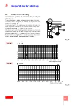
Page 56: ...14 5 5 2 20 20 20076847...
Page 57: ...15 5 5 3 1 4 2 3 5 6 7 1 2 0 3 20 4 5 20 130 1 4 5 4 130 22 21 D1500 3 2 4 1 22 1 2 3 4 D1499...
Page 58: ...16 5 MAN 3 1 130 90 2 22 2 22 20 2 2...
Page 60: ...18 5 5 7 70 A 187 V 100 A c c 100 F 1V c c 5 8 1 2 3 4 5 1 2 3 4 5 6 D1143 26...
Page 61: ...19 6 6 1 1 2 3 VR VR VS VR...
Page 62: ...20 6...
Page 63: ......


