11
4
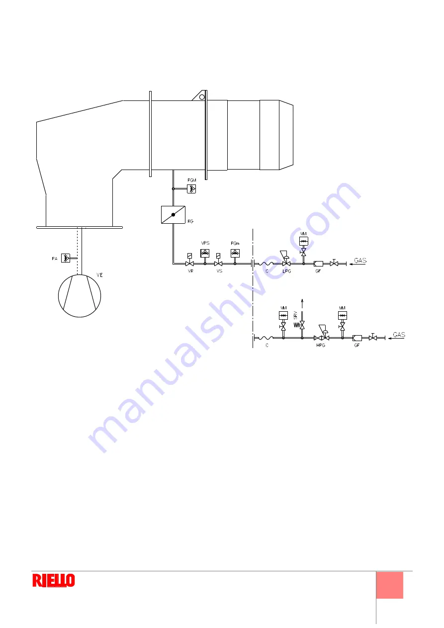
Alimentazione al bruciatore
4.1
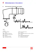
Schema generale di alimentazione gas (esempio)
D7543
Legenda
C
Giunto antivibrante
GF
Filtro gas
HPG
Regolatore alta pressione gas
LPG
Regolatore bassa pressione gas
MM
Manometro
PA
Pressostato aria di minima
PGM
Pressostato gas di massima
PGm
Pressostato gas di minima
RG
Farfalla gas
SRV
Valvola limitatrice di pressione con scarico in atmosfera
VE
Ventilatore
VPS
Controllo di tenuta elettrovalvole gas
VR
Elettrovalvola di regolazione gas
VS
Elettrovalvola di sicurezza gas
0,5 ÷ 4 bar
max. 500 mbar
Fig. 16
Summary of Contents for DB 6 SM CO1 A0
Page 2: ......
Page 43: ...1...
Page 44: ...2 1 3 3 3 2 4 4 4 5 6 8 9 3 10 10 10 10 10 4 11 11 12 5 13 13 14 15 15 17 18 18 6 19 19...
Page 47: ...5 2 2 3 1 2 3 4 5 6 7 8 9 10 11 UV 12 13 14 15 16 17 18 19 20 21 M12x16 2 20076243...
Page 49: ...7 2 DN 80 160 18 4 54 5 4 9 5 3 8 0 M18 D8325 7 8 D3974 9 D7549 DB6 SM...
Page 53: ...11 4 4 1 D7543 C GF HPG LPG MM PA PGM PGm RG SRV VE VPS VR VS 0 5 4 bar 500 mbar 16...
Page 54: ...12 4 4 2 MB PA PGM SM UV UV TA TB D9854 17...
Page 56: ...14 5 5 2 20 20 20076847...
Page 57: ...15 5 5 3 1 4 2 3 5 6 7 1 2 0 3 20 4 5 20 130 1 4 5 4 130 22 21 D1500 3 2 4 1 22 1 2 3 4 D1499...
Page 58: ...16 5 MAN 3 1 130 90 2 22 2 22 20 2 2...
Page 60: ...18 5 5 7 70 A 187 V 100 A c c 100 F 1V c c 5 8 1 2 3 4 5 1 2 3 4 5 6 D1143 26...
Page 61: ...19 6 6 1 1 2 3 VR VR VS VR...
Page 62: ...20 6...
Page 63: ......


