20023724
13
GB
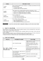
To reset the control box after the diagnostics display, press the lockout-reset button.
6.
FAULTS / SOLUTIONS
Here below you can find some causes and the possible solutions for some problems that could cause a
failure to start or a bad working of the burner.
A fault usually makes the lock-out lamp light which is situated inside the reset button of the control box
(4, fig. 1, page 2).
When lock out lamp lights the burner will attempt to light only after pushing the reset button. After this if
the burner functions correctly, the lock-out can be attributed to a temporary fault.
If however the lock out continues the cause must be determined and the solution found.
6.1
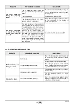
START-UP PROBLEMS
SIGNAL
PROBABLE CAUSE
3 pulses
Min. air pressure switch does not close or is already closed before the limit
thermostat closed:
– air pressure switch faulty;
– air pressure switch incorrectly regulated.
4 pulses
Light present in the chamber before the burner’s switching on or off:
– presence of a strange light before or after the limit thermostat switching over;
– presence of a strange light during pre-ventilation;
– presence of a strange light during post-ventilation.
6 pulses
Loss of ventilation air:
– air loss during pre-ventilation;
– air loss during and after safety time.
7 pulses
Loss of flame during operations:
– poor burner regulation (insufficient gas);
– faulty or soiled gas valves;
– short circuit between ionisation probe and earth.
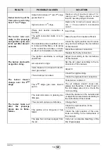
FAULTS
POSSIBLE CAUSES
SOLUTION
The burner doesn’t
start when the limit
thermostat closes.
Lack of electrical supply.
Check presence of voltage in the L1 - N
clamps of the 7 pin plug.
Check the condition of the fuses.
Check that safety thermostat is not
lock out.
Lack of gas.
Check the manual cock opening.
Check that the valves charge over to
the opening position and there are not
short circuits.
The gas pressure switch does not
close its contact.
Adjust them.
The connections in the control box
are wrongly inserted.
Check and connect all the plugs.
The air pressure switch is changed
over to the operational position.
Replace the pressure switch.
ATTENTION
Summary of Contents for BS1D
Page 2: ......
Page 31: ...20023724 13 6 4 1 2 6 1 4 6 7 7 L1 N 1 2 1 2 1 2 1 2 1 1 1 3 4 4...
Page 32: ...20023724 14 CN 3 2 2 2 13 9 9 9 4 2...
Page 33: ...20023724 15 CN 6 2 4...
Page 34: ...20023724 16 CN 7 7 1 7 2...
Page 35: ......


