20023724
12
GB
5.
MAINTENANCE
Disconnect the electric supply to the burner by switching off the main power switch and close the
gas shut-off valve before maintaining or checking the system.
The burner requires scheduled maintenance that must be carried out by qualified personnel and in compli-
ance with local legislation.
Scheduled maintenance is vital for the smooth operation of the burner; it avoids waste of fuel and reduces
harmful emissions into the atmosphere.
THE FUNDAMENTAL OPERATIONS TO CARRY OUT ARE AS
FOLLOWS:
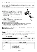
Check at regular intervals that the holes of the gas head are
not obstructed. If they are, clean them with a suitable tool as
shown in the figure 11.
Check there are no occlusions or obstructions in the inlet or
return pipes, in the air suction areas and in the combustion
product waste pipe.
Check that the burner and gas train electrical connections are
correct.
Check that the positioning of the air pressure test point (6, fig.
1, page 2) is correct.
Check that the gas train is suited to the burner capacity, the type
of gas used and the network gas pressure.
Check that the positioning of the combustion head is correct
and that it is properly fixed to the boiler.
Check that the air damper is positioned correctly.
Check that the ionisation probe and the electrode are positioned correctly (see fig. 5, page 6).
Check that the air pressure switch and the gas pressure switch are set correctly.
Leave the burner operating in steady state for approx. ten minutes, checking to ensure that all elements
indicated herein have the proper settings for 1
st
and 2
nd
stage.
Then carry out the analysis of the combustion by checking:
CO
2
percentage (%);
CO content (ppm);
NOx content (ppm);
Ionisation current (
μ
A);
Flue gases temperature at the stack.
5.1
VISUAL DIAGNOSTIC CONTROL BOX
The control box has a diagnostic function that can identify the likely causes of any malfunctions (indicator:
RED LED
).
In order to be able to use this function, press and hold the reset button for at least 3 seconds from when the
appliance is made safe (
lock-out
).
The control box sends a sequence of pulses that are repeated at 2-second intervals.
The sequence of pulses issued by the control box identifies the possible types of malfunction, which are
listed in the table below.
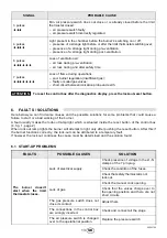
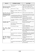
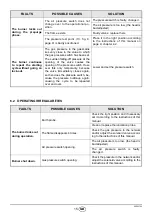
SIGNAL
PROBABLE CAUSE
2 pulses
The flame does not stabilise at the end of the safety time:
– faulty ionisation probe;
– faulty or soiled gas valves;
– neutral/phase exchange;
– faulty ignition transformer
– poor burner regulation (insufficient gas).
Fig. 11
E9252
2s
Pulses
Pulses
RED LED illuminated
press reset for 3 sec.
Interval
Summary of Contents for BS1D
Page 2: ......
Page 31: ...20023724 13 6 4 1 2 6 1 4 6 7 7 L1 N 1 2 1 2 1 2 1 2 1 1 1 3 4 4...
Page 32: ...20023724 14 CN 3 2 2 2 13 9 9 9 4 2...
Page 33: ...20023724 15 CN 6 2 4...
Page 34: ...20023724 16 CN 7 7 1 7 2...
Page 35: ......


