background image

20023724

16

GB

7.

SAFETY WARNINGS

The dimension of the boiler’s combustion chamber must respond to specific values, in order to guarantee a
combustion with the lowest polluting emissions rate. 
The Technical Service Personnel will be glad to give you all the imformation for a correct matching of this
burner to the boiler.

This burner must only be used for the application it was designed for. 

The manufacturer accepts no liability within or without the contract for any damage caused to people, ani-
mals and property due to installation, adjustment and maintenance errors or to improper use.

7.1

BURNER IDENTIFICATION

The Identification Plate on the product gives the serial number, model and main technical and performance
data. If the Identification Plate is tampered with, removed or missing, the product cannot be clearly identi-
fied thus making any installation or maintenance work potentially dangerous.

7.2

BASIC SAFETY RULES

Children or inexpert persons must not use the appliance.

Under no circumstances must the intake grids, dissipation grids and ventilation vents in the installation
room be covered up with cloths, paper or any other material.

Unauthorised persons must not attempt to repair the appliance.

It is dangerous to pull or twist the electric leads.

Cleaning operations must not be performed if the appliance is not disconnected from the main power
supply. 

Do not clean the burner or its parts with inflammable substances (e.g. petrol, alcohol, etc.). The cover
must be cleaned with soapy water.

Do not place anything on the burner.

Do not block or reduce the size of the ventilation vents in the installation room.

Do not leave containers and inflammable products in the installation room.

Summary of Contents for BS1D

Page 1: ...per installazione uso e manutenzione 20023724 1 05 2010 Forced draught gas burners CODE MODEL TYPE 20024345 BS1D 915 T1 20024417 BS2D 916 T1 20023689 BS3D 917 T1 20023768 BS4D 918 T1 GB CN Two stage...

Page 2: ......

Page 3: ...as feeding line 7 3 7 Electrical wiring 8 4 WORKING 9 4 1 Combustion adjustment 9 4 2 Combustion head setting 9 4 3 Air damper setting 10 4 4 Combustion check 10 4 5 Air pressure switch 11 4 6 Burner...

Page 4: ...gram on page 8 MULTIBLOC ROTATION KIT There is a special kit available that can be used to install the burner turned 180 as illustrated on page 5 in position 5 in the section entitled 3 1 WORKING POSI...

Page 5: ...ary 230V 0 2A Secondary 8 kV 12 mA Absorbed electrical power 0 15 kW 0 18 kW 0 35 kW 0 53 kW 1 Reference conditions Temp 20 C Barometric pressure 1013 mbar Altitude 0 m above sea level COUNTRY AT IT D...

Page 6: ...r dimensions are similar to those shown in the dia gram EN 676 For applications where the boiler does not conform to EN 303 or where the combustion chamber is much smaller than the dimen sions given i...

Page 7: ...POSITION The burner is designed for operation in position 1 only Installation in positions 2 3 5 6 and 7 is not recommended as it is likely to hinder the unit s proper operation since air damper closu...

Page 8: ...ion head tighten the flange with the screws 6 and lock the loose screw 4 N B The burner can be fixed with the variable dimension A see fig 4 Anyway make sure that the combustion head crosses completel...

Page 9: ...e 3 6 GAS FEEDING LINE GAS TRAIN MATCHED BURNER CONNECTIONS USE TYPE CODE INLET OUTLET MB ZRDLE 405 B01 3970539 BS1D Rp 1 2 Flange 1 Natural gas and LPG MB ZRDLE 405 B01 3970540 BS2D Rp 3 4 Flange 2 N...

Page 10: ...the bridge TESTING Check the burner has stopped by opening the thermostats Check that the burner is blocked by opening the connector CN1 inserted in the probe red wire and located outside the control...

Page 11: ...g rod set at set point 3 as shown in the diagram The diagram is for indication purposes to as sure good working from the burner we sug gest adjusting the combustion head according to the boiler REMOVI...

Page 12: ...output follow the instructions below Output ratio between 1st and 2nd stage must be no more than 1 2 Example for BS3D 2nd stage output required 140 kW Minimum 1st stage output no less than 70 kW Whate...

Page 13: ...ns cutting off the fuel supply to the valves To use this function the reset button must be pressed when the limit thermostat is not switched over BURNER SWITCHED OFF Post ventilation time can be set t...

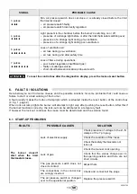
Page 14: ...er Check that the air damper is positioned correctly Check that the ionisation probe and the electrode are positioned correctly see fig 5 page 6 Check that the air pressure switch and the gas pressure...

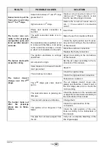
Page 15: ...re the burner s switching on or off presence of a strange light before or after the limit thermostat switching over presence of a strange light during pre ventilation presence of a strange light durin...

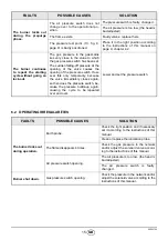
Page 16: ...he ignition electrodes is wrongly positioned Adjust it according to the instructions of this manual Air output is too high Set the air output according to the in structions of this manual Valve brake...

Page 17: ...of the pressure switch How ever this only temporarily because the valve immediately closes again so then does the pressure switch be cause the pressure builds up again causing the cycle to be repeate...

Page 18: ...Plate is tampered with removed or missing the product cannot be clearly identi fied thus making any installation or maintenance work potentially dangerous 7 2 BASIC SAFETY RULES Children or inexpert...

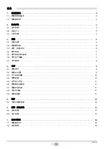
Page 19: ...24 1 CN 1 2 1 1 2 1 2 2 2 3 2 1 3 2 2 3 2 3 4 3 5 3 1 5 3 2 6 3 3 6 3 4 7 3 5 7 3 6 7 3 7 8 4 9 4 1 9 4 2 9 4 3 10 4 4 10 4 5 11 4 6 11 4 7 11 4 8 11 4 9 11 5 12 5 1 12 6 13 6 1 13 6 2 15 7 16 7 1 16...

Page 20: ...No 17 No 1 4 No 1 No 1 1 2 RS 20 8 180 5 3 1 5 1 2 6 3 7 4 5 6 7 8 9 10 4 IP 40 EN 60529 EMC 89 336 CEE 2004 108 CE 73 23 CEE 2006 95 CE 98 37 EEC 2006 42 EC EN 676 EN 676 SVGW Fire Brigade VKF 0 9 0...

Page 21: ...0 C 1013 mbar 0 m AT IT DK CH GB IE DE FR NL LU BE II2H3B P II2H3P II2ELL3B P II2Er3P II2L3B P II2E3B P I2E R B I3P G20 H 20 G25 L 25 20 25 25 G20 E 20 20 25 20 25 A B C D E F G H I L T M N O P R S 91...

Page 22: ...03 EN 676 mbar mbar 50 100 150 200 250 0 0 8 1 6 2 4 3 2 4 0 250 000 200 000 100 000 50 000 10 20 30 40 50 60 70 80 90 100 0 0 4 0 8 1 2 1 6 2 0 2 4 80 000 70 000 60 000 50 000 40 000 30 000 10 000 20...

Page 23: ...m3 8 570 kcal m3 G20 0 mbar 916T1 9 3 mbar M2 7 3 6 3 3 1 1 2 3 6 7 5 MULTIBLOC 4 mbar D8933 0 50 100 150 200 kW 0 50 000 100 000 150 000 kcal h 10 8 6 4 2 0 250 200 000 12 9 1 5 T 1 916T1 917T1 918T1...

Page 24: ...6 CN 3 2 3 3 4 4 2 5 1 3 4 2 5 6 4 A 4 3 3 2 3 4 A 915 T1 116 70 916 T1 114 100 917 T1 128 110 918 T1 167 5 145 A D5012 D5011 S7002 D6088 0 3 3 5 0 3 A 5 1 3 2 4 3 5 2 4 2 915T1 916T1 917T1 918T1 A 17...

Page 25: ...B01 3970540 BS2D Rp 3 4 2 LPG MB ZRDLE 407 B01 3970538 BS2D Rp 3 4 2 LPG MB ZRDLE 407 B01 3970541 BS3D BS4D Rp 3 4 3 150kW LPG MB ZRDLE 410 B01 3970542 BS3D BS4D Rp 1 1 4 3 LPG MB ZRDLE 412 B01 39705...

Page 26: ...20023724 8 CN 3 7 230V 50Hz B5 C CN1 E h MV PA PG RS SM SO D4627 S3 230V 0 5A max T6A TB TL TR TS V10 V11 1 V12 2 X XP 1 mm2 T6 T8 2 CN1 8 7 TB A A 8 1 1 2 Nm A 24 TL TL 24 A 8 E9250 MG569...

Page 27: ...2 4 2 9 6 2 1 9 3 BS3D 100 kW 90 110 kW 3 3 5 4 10 7 1 2 1 7 3 4 Nm 13 1 F 9 S7006 D8934 170 000 50 000 210 000 130 000 90 000 10 000 kcal h kW 0 8 2 4 6 210 10 50 70 110 130 150 170 190 30 90 230 250...

Page 28: ...0 5 mbar 1 2 1 2 1 2 BS3D 2 140 kW 70 kW 1 BS3D 2 110 kW 1 65 kW 4 4 4 5 A CN1 8 10 EN 676 1 2 1 3 CO2 0 O2 CO2 CO mg kWh NOx mg kWh 1 2 1 3 G 20 11 7 9 7 9 0 100 170 G 25 11 5 9 5 8 8 100 170 G 30 14...

Page 29: ...20023724 11 CN 4 5 CO 1 10 000 ppm CO 1 4 6 4 1 2 4 7 3 4 8 TL TL 6 5 LED 1 5 LED 1 5 LED 20 TL 4 9 1 TL 40 3 40 3 A 5 25 D5016 1 1 2 2 A...

Page 30: ...20023724 12 CN 5 11 6 1 2 6 5 10 1 2 CO2 CO ppm NOx ppm I A 5 1 LED 3 LED 2 2 3 11 E9252 2 LED 3...

Page 31: ...20023724 13 6 4 1 2 6 1 4 6 7 7 L1 N 1 2 1 2 1 2 1 2 1 1 1 3 4 4...

Page 32: ...20023724 14 CN 3 2 2 2 13 9 9 9 4 2...

Page 33: ...20023724 15 CN 6 2 4...

Page 34: ...20023724 16 CN 7 7 1 7 2...

Page 35: ......

Page 36: ...I 37045 Legnago VR Tel 39 0442 630111 http www riello it http www rielloburners com Manufacturing site Riello Heating Equipment Shanghai CO LTD No 388 Jinbai Road Jinshan Industrial Zone 201506 Shang...

Reviews: