background image

29

MERKE
Der  Stellantrieb  folgt  der  Einstellung  von  Nok-
ken  III  nur  bei  Reduzierung  des  Winkels.  Zur
Vergrößerung  des  Nockenwinkels  zuerst  durch
die  Taste  “Leistungserhöhung”  den  Winkel  des
Stellantriebs  vergrößern,  dann  den  Nockenwin-
kel  III  vergrößern  und  schließlich  durch  die
Taste “Leistungsminderung” den Stellantrieb auf
Mindestleistungsstellung zurückgehen lassen.

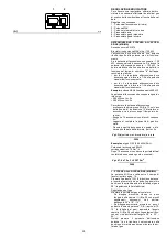
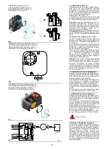
Zur  Einstellung  des  Nocken  III  ist  der  eingera-
stete Deckel 1), s. Abb.(B) abzunehmen, die ent-
sprechende Passfeder 2) herauszuziehen und in
den Schlitz des Nocken III einzustecken.

Lufteinstellung
Das  Anfangsprofil  des  Nocken  4)(A)  über  die
Nockenschrauben  in  der  Öffnung  6)(A)  verän-
dern.  Die  erste  Schraube  möglichst  nicht  ver-
drehen,  mit  dieser  wird  die  Luftklappe  ganz
geschlossen. 

2 - HÖCHSTLEISTUNG
Die Höchsteistung ist im Regelbereich auf Seite
14 auszuwählen.
In  der  vorhergehenden  Beschreibung  ist  der
Brenner  auf  der  Mindestleistung  in  Betrieb
geblieben.  Nun  auf  die  Taste  2)(A)S.26  “Lei-
stungssteigerung”  drücken,  bis  der  Stellantrieb
gleichzeitig  die  Luftklappe  und  die  Gasdrossel
auf 90° geöffnet hat auf 90°.
Gaseinstellung
Den Gasdurchsatz am Zähler messen.
Als Richtwert ist der Durchsatz aus den Tabellen
auf  Seite  16  zu  entnehmen,  einfach  den  Gas-
druck am Manometer, s. Abb. (D)S. 24, ablesen
und die Hinweise auf Seite 17 befolgen.
- Falls er herabgesetzt werden muß, den Aus-

trittsgasdruck verringern, und, wenn er schon
auf dem Mindestdruckwert ist, das Regelven-
til VR etwas schließen.

- Falls er erhöht werden muß, den Austrittsgas-

druck erhöhen.

Lufteinstellung
Über die Schrauben des Nocken im Inneren der
Öffnung  6)(A)  das  Endprofil  des  Nocken  4)(A)
verändern.
- Zur  Erhöhung  des  Luftdurchsatzes  die

Schrauben zudrehen.

- Zur  Reduzierung  des  Luftdurchsatzes  die

Schrauben abdrehen.

3 - ZWISCHENLEISTUNGEN
Gaseinstellung
Keine Einstellung ist erforderlich.

Lufteinstellung
Auf  die  Taste  2)(A)S.26  “Leistungserhöhung”
leicht  drücken,  so  daß  eine  neue  Schraube
5)(A)  innerhalb  der  Öffnung  6)(A)  sichtbar  ist.
Die Schraube einstellen , bis eine optimale Ver-
brennung  erreicht  wird.  Mit  den  anderen
Schrauben gleich verfahren.
Darauf  achten,  daß  die  Änderung  des  Nocken-
profils progressiv ist.
Brenner durch Schalter 1)(A)S.26, Stellung OFF,
abschalten,  den  Nocken  mit  variablem  Profil
durch  vertikale  Positionierung  des  Schlitzes
2)(A)  am  Stellantrieb  entsperren, und  den  Nok-
ken mehrmals von Hand vor- und zurückdrehen:
die Bewegung muß sanft und ungehindert erfol-
gen.
Darauf  achten,  daß  die  Schrauben  an  den
Enden  des  vorab  eingestellten  Nockens  für  die
Öffnung der Luftklappe auf der Höchst- und Min-
destleistung nicht versetzt werden.

MERKE
Nach  Einstellung  der  Höchst-,  Mindest-  und
Zwischenleistungen  ist  die  Zündung  nochmals
zu  überprüfen.  Der  Schalldruckpegel  muß  dem
der  anschließenden  Betriebsphase  entspre-
chen.  Bei  Verpuffungen  sollte  der  Zünddurch-
satz reduziert werden.

NOTE
The servomotor follows the adjustment of cam
III  only  when  the  cam  angle  is  reduced.  If  it  is
necessary  to  increase  the  cam  angle,  first
increase the servomotor angle with the key “out-
put  increase”,  then  increase  the  cam  III  angle,
and at the end bring the servomotor back to the
MIN  output  position  with  the  key  ”output
decrease”.

In order to adjust cam III, remove press-fit cover
1), as shown in fig.(B), extract the relevant key 2)
from inside, and fit it into the keyway in cam III.

Adjustment of air delivery
Progressively  adjust  the  starting  profile  of  cam
4)(A) by turning the screws working through the
access hole 6)(A). 
It  is  preferable  not  to  turn  the  first  screw  since
this is used to set the air gate valve to its fully-
closed position. 

2 - MAX. OUTPUT
Max. output of the burner must be set within the
firing rate range shown on page 14.
In the above instructions we left running in MIN.
output  operation.  Now  press  button  2)(A)p.26
“increase  output”  and  keep  it  pressed  until  the
servomotor  has  opened  the  air  gate  valve  and
the gas butterfly valve by 90°.
Gas calibration
Measure the gas delivery at the meter.
A guideline indication can be calculated from the
tables on page 16, simply read off the gas pres-
sure on the manometer, see fig. (D) on page 24,
and follow the instructions on page 17.
- If delivery needs to be reduced, decrease the

outlet  gas  pressure  and,  if  it  is  already  very
low, slightly close adjustment valve VR.

- If  delivery  needs  to  be  increased,  increase

outlet gas pressure.

Adjusting air delivery
Progressively adjust the end profile of cam 4)(A)
by  turning  the  cam  adjustment  screws  as  they
appear through the access opening 6)(A).
- Turn  the  screws  clockwise  to  increase  air

delivery.

- Turn  the  screws  anti-clockwise  to  reduce  air

delivery.

3 - INTERMEDIATE OUTPUTS
Adjustment of gas delivery
No adjustment of gas delivery is required.

Adjustment of air delivery
Press the key 2)(A)p.26 “output increase” a little
so that a new screw 5)(A) appears in the open-
ing  6)(A),  adjust  it  until  optimal  combustion  is
obtained.  Proceed  in  the  same  way  with  the
other screws.
Take  care  that  the  cam  profile  variation  is  pro-
gressive.
Switch the burner off with the switch  1)(A)p.26,
free  the  variable  profile  cam  putting  the  servo-
motor slot 2)(A) in a vertical position and check
more  than  once,  rotating  the  cam  forward  and
backward  by  hand,  that  the  movement  is  soft
and smooth, without sticking.
As  far  as  is  possible,  try  not  to  move  those
screws at  the  ends  of  the cam  that were previ-
ously adjusted for the opening of the air gate to
MAX and MIN output.

NOTE
Once you have finished adjusting outputs MAX -
MIN  -  INTERMEDIATE,  check  ignition  once
again:  noise  emission  at  this  stage  must  be
identical  to  the  following  stage  of  operation.  If
you  notice  any  sign  of  pulsations,  reduce  the
ignition stage delivery.

NOTE
Le servomoteur ne suit le réglage de la came
III que quand on réduit l'angle de la came. Avant
d’augmenter  l’angle  de  la  came,  augmenter
d’abord augmenter l’angle du servomoteur avec
le bouton “augmentation de la puissance”, aug-
menter  ensuite  l’angle  de  la  came  IIII  et  enfin
reporter  le  servomoteur  en  position  de  puis-
sance  MIN  avec  le  bouton  “diminution  de  la
puissance”.

Pour régler éventuellement la  came III,  enlever
le couvercle  1) enclenché par pression comme
indiqué sur la fig. (B),  retirer la clavette 2) située
à l’intérieur et placer celle-ci dans la fente de la
came III.

Réglage de l'air

Modifier  en  progression  le  profil  initial  de  la
came 4)(A) en agissant sur les vis de celle-ci qui
apparaissent à l’intérieur de l’ouverture 6)(A). Si
possible, Ne pas serrer  la première  vis, si  pos-
sible il s'agit de la vis qui ferme complètement le
volet de l'air.

2 - PUISSANCE MAXIMUM
La puissance maximum doit être choisie dans la
plage indiqué à la page 14.
La description qui précède concerne un brûleur
allumé et fonctionnant à la puissance minimum.
Appuyer  ensuite  sur  le  bouton  2)(A)p.26  “aug-
mentation de la puissance” sans le relâcher  et
continuer à appuyer jusqu’à ce que le servomo-
teur  ouvre  le  volet  d’air  et  la  vanne  papillon  du
gaz à 90°.
Réglage du gaz
Mesurer le débit du gaz sur le compteur.
A titre indicatif, ce débit peut être trouvé sur les
tableaux à la page 16. Il suffit de lire la pression
du  gaz  sur  le  manomètre,  comme  indiqué  fig.
(D)  page  24,et  de  suivre  les  indications  de  la
page 17.
- Diminuer la pression du gaz à la sortie s'il faut

la  réduire  et  fermer  légèrement  la  vanne  de
réglage  si  elle  est  déjà  au  minimum.  fermer
un peu la vanne de réglage VR.

- Augmenter  la  pression  du  gaz  à  la  sortie  s’il

faut l’augmenter.

Réglage air
Modifier en progression le profil final de la came
4)(A)  en  agissant  sur  les  vis  de  celle-ci  qui
apparaissent à l’intérieur de l’ouverture 6)(A).
- Pour augmenter le débit d'air serrer les vis.
- Pour diminuer celui-ci, desserrer les vis.

3 - PUISSANCES INTERMEDIAIRES
Réglage du gaz
Aucun réglage n'est nécessaire.

Réglage de l'air
Appuyer  légèrement  sur  le  bouton  2)(A)p.26
“augmentation de la puissance” afin qu’une nou-
velle vis 5)(A) apparaise à l’intérieur de l’ouver-
ture 6)(A), la régler pour obtenir une combustion
parfaite.  Procéder  de  la  même  façon  avec  les
vis successives.
Contrôler si la variation du profil de la came est
progressive.
Eteindre  le  brûleur  en  actionnant  l'interrupteur
1)(A)p.26, position OFF, détacher la came à pro-
fil variable en mettant la fente 2)(A) du servomo-
teur  en  position  verticale  et  contrôler  plusieurs
fois,  en  tournant  manuellement  la  came  vers
l’avant  et  vers  l’arrière,  si  le  mouvement  est
souple et sans accrocs.
Si  possible,  faire  en  sorte  veiller  à  ne  pas
déplacer les vis aux extrémités car elles ont été
réglées précédemment pour l'ouverture du volet
à la puissance MAX. et MIN.

NOTE
Contrôler  l’allumage  dès  que  le  réglage  des
puissances MAX – MIN – intermédiaires est ter-
miné. Celui-ci doit produire un son identique au
son  du  fonctionnement  qui  s'ensuit.  En  cas  de
saccades,  Réduire  le débit à  l’allumage  en  cas
de saccades.

Summary of Contents for 882 T80

Page 1: ...d aria soffiata Gas Gebl sebrenner Forced draught gas burners Br leurs gaz air souffl Funzionamento bistadio progressivo o modulante Zweistufig gleitender oder modulierender Betrieb Progressive two st...

Page 2: ...14 30 UE Compatibilit Elettromagnetica La qualit viene garantita mediante un sistema di qualit e management certificato secondo UNI EN ISO 9001 Dichiarazione del costruttore RIELLO S p A dichiara che...

Page 3: ...agnetische Vertr glichkeit Die Qualit t wird durch ein gem UNI EN ISO 9001 zertifiziertes Qualit ts und Managementsystem garantiert Erkl rung des Herstellers Die Firma RIELLO S p A erkl rt dass die fo...

Page 4: ...ctive EMC 2014 30 UE Electromagnetic Compatibility The quality is guaranteed by a quality and management system certified in accordance with UNI EN ISO 9001 Manufacturer s Declaration RIELLO S p A dec...

Page 5: ...MC 2014 30 UE Compatibilit lectromagn tique La qualit est garantie gr ce un syst me de qualit et de gestion certifi conforme UNI EN ISO 9001 D claration du constructeur RIELLO S p A d clare que les pr...

Page 6: ...o cos indicate 1 A Particolare 1 della figura A nella stessa pagina del testo 1 A p 8 Particolare 1 della figura A riportata a pagina 8 I INHALT TECHNISCHE ANGABEN Seite 9 Elektrische daten 9 Brennerb...

Page 7: ...s text 1 A p 8 part 1 of figure A page number 8 GB INDEX DONNEES TECHNIQUES page 11 Elektrische Daten 11 Description br leur 13 Emballage Poids 13 Encombrement 13 Equipement standard 13 Plage de puiss...

Page 8: ...8 2 8 13 7 0 Densit assoluta kg Sm3 0 71 0 78 Portata massima Sm3 h 90 104 5 Pressione alla portata massima 2 mbar 15 3 22 5 Funzionamento Intermittente min 1 arresto in 24 ore Due stadi progressivi...

Page 9: ...2 8 13 7 0 Reindichte kg Sm3 0 71 0 78 H chstdruchsatz Sm3 h 90 104 5 Druck bei H chstleistung 2 mbar 15 3 22 5 Betrieb Intermittierend min 1 Abschaltung in 24 Std Gleitend zweistufig modulierend mit...

Page 10: ...3 9 45 8 2 8 13 7 0 Absolute density kg Sm3 0 71 0 78 Max delivery Sm3 h 90 104 5 Pressure at max delivery 2 mbar 15 3 22 5 Operation On Off 1 stop min each 24 hours Progressive two stage or modulatin...

Page 11: ...calorifique inf rieur kWh Sm3 Mcal Sm3 9 45 8 2 8 13 7 0 Densit absolue kg Sm3 0 71 0 78 D bit maximum Sm3 h 90 104 5 Pression au d bit max 2 mbar 15 3 22 5 Fonctionnement Intermittent 1 arr t min en...

Page 12: ...sonda di ionizza zione 24 Pressostato gas di massima 25 Contattore motore e rel termico con pul sante di sblocco 26 Protezione motore Vi sono due possibilit di blocco del bruciatore BLOCCO APPARECCHIA...

Page 13: ...ation probe cable 24 Maximum gas pressure switch 25 Motor contact maker and thermal cutout with reset button 26 Engine protection Two types of burner failure may occur CONTROL BOX LOCK OUT if the cont...

Page 14: ...o 50 cm lunghezza 1 5 m CALDAIE COMMERCIALI C L abbinamento bruciatore caldaia non pone pro blemi se la caldaia omologata CE e le dimen sioni della sua camera di combustione sono vicine a quelle indic...

Page 15: ...combustion chamber Example Output 350 Mcal h diameter 50 cm length 1 5 m COMMERCIAL BOILERS C The burner boiler combination does not pose any problems if the boiler is CE approved and its combustion...

Page 16: ...fissata la potenza MAX alla quale si desidera funzioni il bruciatore trovare nella tabella relativa al bruciatore con siderato il valore di potenza pi vicino al valore desiderato Leggere sulla destra...

Page 17: ...1 This value serves as a rough guide the effective delivery must be measured at the gas meter To calculate the required gas pressure at test point 1 B set the maximim output required from the burner...

Page 18: ...IA D Prima di fissare il bruciatore alla caldaia verifi care dall apertura del boccaglio se la sonda e l elettrodo sono correttamente posizionati come in D Separare quindi la testa di combustione dal...

Page 19: ...R D Before securing the burner to the boiler check through the blast tube opening to make sure that the flame sensor probe and the ignition electrode are correctly set in position as shown in D Now de...

Page 20: ...aria va effettuata sulla tacca 7 5 come in fig A Terminata la regolazione della testa rimontare il bruciatore sulle guide 3 C a circa 100 mm dal manicotto 4 C bruciatore nella posizione illu strata d...

Page 21: ...of the flange Example MAX output 500 Mcal h If we consult diagram B we find that for this output air must be adjusted using notch 7 5 as shown in figs A Once you have finished setting up the head refi...

Page 22: ...ta di combustione P2 Pressione a monte valvole regolatore P3 Pressione a monte del filtro L Rampa gas fornita a parte con il codice indicato in tab C L1 A cura dell installatore LEGENDA TABELLA C C T...

Page 23: ...n accordance with the standard EN 676 gas valve leak detection control devices are compulsory for burners with maximum outputs of more than 1200 kW 8 Gasket 9 Gas adjustment butterfly valve 10 Max gas...

Page 24: ...che esse siano come sotto riportato Camma I 90 Limita la rotazione verso il massimo Con il bru ciatore funzionante alla potenza MAX la farfalla del gas deve risultare tutta aperta 90 Camma I I 0 Limi...

Page 25: ...am and the gas butterfly valve The angle of rotation of the servomotor is equal to the angle on the graduated sector controlling the gas butterfly valve The servomotor rotates through 90 in 24 seconds...

Page 26: ...a spina presa 23 A p 12 sul cavo della sonda di ionizzazione il bruciatore si accende e va in blocco dopo il tempo di sicu rezza Eseguire 10 accensioni con blocchi consecu tivi Leggere al contatore la...

Page 27: ...quantity of gas burned This quantity must be equal to or lower than the quantity given by the formula for ts 3s Example for gas G 20 9 45 kWh Sm3 ignition output 400 kW corresponding to 47 6 Sm3 h Af...

Page 28: ...ata d aria svitare le viti 3 POTENZE INTERMEDIE Regolazione del gas Non occorre alcuna regolazione Regolazione dell aria Premere un poco il pulsante 2 A p 26 aumento potenza in modo che una nuova vite...

Page 29: ...elivery needs to be increased increase outlet gas pressure Adjusting air delivery Progressively adjust the end profile of cam 4 A by turning the cam adjustment screws as they appear through the access...

Page 30: ...ressostato gas di massima dopo aver effettuato tutte le altre rego lazioni del bruciatore con il pressostato gas di massima regolato a fine scala B Con il bruciatore funzionante alla potenza mas sima...

Page 31: ...ressure switch after having performed all other burner adjustments with the maximum gas pressure switch set to the end of the scale B With the burner operating at MAX output reduce the adjustment pres...

Page 32: ...elettrica continua comunque a controllare la presenza della fiamma e la cor retta posizione deI pressostatI aria e gas di massima Se la temperatura o la pressione bassa per cui il termostato pressosta...

Page 33: ...r temperature control point C The control box continues however to check that the flame is present and that the air pres sure switch is in the correct position If the temperature or pressure is low an...

Page 34: ...he di gas Controllare che non vi siano fughe di gas sul condotto contatore bruciatore Filtro del gas Sostituire il filtro del gas quando sporco Visore fiamma Pulire il vetrino del visore fiamma A Test...

Page 35: ...Gas filter Change the gas filter when it is dirty Flame inspection window Clean the flame inspection window A Combustion head Open the burner and make sure that all compo nents of the combustion head...

Page 36: ...iglia 9 in modo che il bruciatore rimanga in quella posizione A questo punto possibile estrarre il distributore del gas 7 dopo aver tolto la vite 8 PER CHIUDERE IL BRUCIATORE A togliere la copiglia 9...

Page 37: ...y back Turn the burner as shown in the figure and fit the split pin 9 into one of the slide bar holes so that the burner remains in position Now extract the gas distributor 7 after having removed the...

Page 38: ...ria mal regolato Regolarlo o sostituirlo 16 Tubetto presa pressione del pressostato ostruito Pulirlo 17 Testa mal regolata Regolarla 18 Alta pressione nel focolare Collegare pressostato aria all aspir...

Page 39: ...sione del gas in rete vicina al valore sul quale regolato il pressostato gas di minima Il calo di pres sione repentino che segue l apertura della valvola pro voca l apertura temporanea del pressostato...

Page 40: ...itung der Druckentnahmestelle des Druckw chters verstopft Reinigen 17 Kopf schlecht eingestellt Einstellen 18 Hoher Unterdruck im Feuerraum Luft Druckw chter an Gebl se Ansaug ff nung anschlie en St r...

Page 41: ...er Gasdruck in der Leitung ist dem am Mindestgas druckw chter eingestellten Wert sehr nahe Der pl tzli che Druckabfall beim ffnen des Ventils bewirkt die ffnung des Druckw chters Dadurch schlie t sich...

Page 42: ...Air pressure switch incorrectly adjusted Adjust or replace 16 Pressure switch pressure test point pipe blocked Clean 17 Poorly adjusted head Adjust 18 High pressure in the furnace Connect air pressure...

Page 43: ...s very close to the value to which the minimum gas pressure switch has been set The sudden drop in pressure after valve open ing causes temporary opening of the pressure switch itself the valve immedi...

Page 44: ...Nettoyer 17 T te mal r gl e R gler 18 Haute pression dans le foyer Raccorder le pressostat air l aspiration du ventilateur Blocage durant la pr ventila tion 19 Contacteur de commande du moteur d fectu...

Page 45: ...ession du gaz en r seau est proche de la valeur a laquelle le pressostat gaz minimum est r gl La chute de pression soudaine suite l ouverture de la vanne pro voque l ouverture temporaire du pressostat...

Page 46: ...ere bypassato In caso contrario se si desidera mantenere il termostato pressostato TL la sua regolazione dev essere tale da non interferire col funzionamento del regolatore RWF40 APPENDICE ATTENZIONE...

Page 47: ...ein dass er den Betrieb des Reglers RWF40 nicht beeinflusst ANHANG ACHTUNG Den Nulleiter nicht mit dem Phasenleiter in der Leitung der Stromversorgung vertauschen Die Folge einer solchen Vertau schung...

Page 48: ...e switch TL it must be adjusted so as not to interfere with the working of the regulator RWF40 APPENDIX ATTENTION Do not invert the neutral with the phase in the electrical supply line An inversion wo...

Page 49: ...ontraire maintenu ne doit pas influer sur le fonctionnement du r gulateur RWF40 ANNEXE ATTENTION Dans la ligne d alimentation lectrique ne pas inverser le neutre avec la phase L inversion ventuelle pr...

Page 50: ...elettrici a cura dell installatore Elektroanschlusse vom Installateur auszuf hren Electrical connections set by installer Raccordements lectriques par l installateur 3 Schema funzionale Betriebsschem...

Page 51: ...51...

Page 52: ...1 3 5 G 1 F 4 D 6 I 6 C 6 9 C 6 9 C 6 6 I 9B C 6 7 C B C 7 B J9 I A C J9 C K 9 C A9 6 A I 09B89 C AB99 C 09B C ABL B8 I B C B98 C B A9 C B I 6 7 C 9 C 6 7 C 9 AI B 7 C B A9 C B A9 C B A9 0 I 0 9 C 0 9...

Page 53: ...5 2 95 3 95 4 0 9 NO54 3 HP3P 877P H76 75Q HP H76 75Q 7 8F G DDR 4 4 4 4 4 4 SH 4H 4H 3 H TJ9 TJ9 3 J H P3P H76 75Q 4 4 J3 3 3 TJ9 TJ9 H U VW J8 H J TJ9 I 39 9 1 3 X X X J Y J4 P J4 P J4 P J4 J Y 3 P...

Page 54: ...8 928 78 82 2295 87582 297 56 21 28 5 N 3 1528 4 9 9 1 4 215 1 9 295 8 8 9 168 1 4 215 8 P 41 1 1 8 1 61 97248 9521 2 379378 1 6156 Q7 7845O9521O28 1 8 1 46B2 61 1 8 1 C8 61 II 1 8 845 61 O42 R 8 8 1...

Page 55: ...XTM Terra mensola X4 Spina 4 poli X5 Spina 5 poli X6 Spina 6 poli X7 Spina 7 poli ZEICHENERKL RUNG SCHEMEN A Steuerger t B Entst rungsfilter BB Komponenten an Bord der Brenner BC Komponenten an Bord...

Page 56: ...elf earth X4 4 pin plug X5 5 pin plug X6 6 pin plug X7 7 pin plug L GENDE SCH MAS ELECTRIQUE A Coffret de s curit B Protection contre parasites radio BB Composants sur br leurs BC Composants sur chaud...

Page 57: ...usa della presenza di INVERTER o in applicazioni dove le lunghezze dei collegamenti del termostato superano i 20 metri disponibile un kit di protezione come interfaccia tra l apparecchiatura e il bruc...

Page 58: ...Signalen ber 10 V m oder bei Anwendungen bei denen die L nge der Anschl sse des Thermostats 20 m berschreiten steht ein Schutz Kit als Schnittstelle zwischen dem Steuerger t und dem Brenner zur Verf...

Page 59: ...ng to the presence of an INVERTER or in applications where the length of the thermostat connections exceeds 20 metres a protection kit is available as an interface between the control box and the burn...

Page 60: ...a pr sence de l INVERTER ou bien dans des applications o les longueurs des connexions du thermostat d passent les 20 m tres un kit de protection est disponible comme interface entre la bo te de contr...

Page 61: ......

Page 62: ......

Page 63: ......

Page 64: ...Con riserva di modifiche nderungen vorbehalten Subject to modifications Sous r serve de modifications RIELLO S p A I 37045 Legnago VR Tel 39 0442 630111 http www riello it http www riello com...

Reviews: