0ML190480RUENUC
page 19 / 24
SECTION
5
CONNECTION TO UPS SYSTEM
The ground terminal of battery cabinet must be connected with ground terminal of UPS cabinet.
NEC article 250 for identify grounding system and sizing grounding conductors
POWER CABLE CONNECTION
Table
4
‐
sizing
conductor
battery
battery
cabinet
OCP
device
*
Field
wiring
bolt
size
torque
Model
A
[q.ty]
x
AWG
in
/
mm
lbf
‐
ft
/Nm
BBX
1900
480V
UL
L6
3U
(55Ah)
200A
4/0
or
[2]
x
2
3/8
"
/
10
22
/
30
BBX
1900
480V
UL
L8
3U
(100Ah)
300A
[2]
x
2/0
*
Included in battery cabinet
cables
are
to
be
connected
to
the
field
terminals
through
Listed
cable
lugs
suitable
for
cable
size
.
When
using
crimp
type
lugs,
follows
the
manufacturer’s
instructions
for
both
crimp
tool
and
lug
CAUTION:
Use at least 75
o
C rated copper wire. Minimum wire size is based on full load ratings applied to
NEC Code Table 310-16. Code may require a larger AWG size than shown in this table because of
temperature, number of conductors in the conduit, or long service runs. Follow local requirements.
CABLE ENTRY OF BATTERY CABINET IS PROVIDED EITHER FROM BOTTOM OR TOP
.
Only properly trained and qualified personnel should perform the UPS installation and initial
start up
1) Make sure that the UPS is not powered.
2) Make sure Battery Circuit breaker is in “off” position
3) Make sure that the cables to connect to UPS cabinet are correctly arranged
4) Make sure the cables are correctly marked with polarity indication (+ and – or red and
black)
5) Connect positive terminal of battery cabinet (+) with positive terminal of UPS cabinet,
connect negative terminal of battery cabinet (-) with negative terminal of UPS cabinet
(see figure).
DO NOT CLOSE BATTERY CIRCUIT BREAKER BEFORE UPS IS OPERATING
Summary of Contents for MASTER HP
Page 1: ...UNINTERRUPTIBLE POWER SUPPLY MASTER HP UL 55 100Ah BATTERY CABINET User Manual ...
Page 2: ...0ML190480RUENUC page 2 24 RPS SpA Viale Europa 7 37045 Legnago VR Italy www riello ups com ...
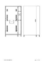
Page 17: ...0ML190480RUENUC page 17 24 ...
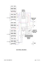
Page 18: ...0ML190480RUENUC page 18 24 ELECTRICAL DRAWING ...
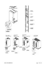
Page 20: ...0ML190480RUENUC page 20 24 ...
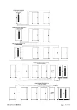
Page 21: ...0ML190480RUENUC page 21 24 ...
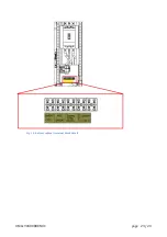
Page 23: ...0ML190480RUENUC page 23 24 Fig 14 battery cabinet terminal block detail ...
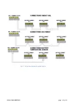
Page 24: ...0ML190480RUENUC page 24 24 Fig 15 Connections diagram of auxiliary signals ...


