0ML190480RUENUC
page 10 / 24
INSPECTING THE EQUIPMENT
If Battery cabinet is not provided with battery blocks installed:
Remove all panels (front, rear, left and right side).
See in the figure the appearance of the cabinet without panels.
The components used for the assembly of battery blocks are always provided and you’ll find
the followings inside the cabinet:
Pos.#
1) Cable 1/0 or #2x1/0 AWG length 360mm (14.17 in.) crimped to “green” or “grey” connector at one
side - 6pcs
2) Cable 1/0 or #2x1/0 AWG length 360mm (14.17 in.) crimped to “red” connector at one side – 2pcs
3) Cable 1/0 or #2x1/0 AWG length 360mm (14.17 in.) crimped to “blue” connector at one side – 2pcs
4) Red and black cable #2x 22 AWG style 1015 800mm (31.5 in.)
5) Shielded cable #2x 22 AWG style 4516 25m (82 ft) (Option)
6) 2 x Cable #2x22 AWG style 2516
7) Cu busbar marked “1” N. 10
8) Cu busbar marked “2” N. 20
9) Cu busbar marked “3” N. 5
10) Cu busbar marked “4” N. 10
11) Screws washers and spring washer to connect busbars to battery terminals
12) Insulated tubing to protect battery terminal connections (cut into 10 pieces about 100mm-3,9 ft-long)
13) Cable tie to close insulated tubing n. 20
14) Straps to secure battery blocks n. 25
15) Insulating sheet – 5pcs
If Battery cabinet is provided with battery blocks installed, don’t remove panels.
Find position 5) and 6) only.
Go to section 5
Summary of Contents for MASTER HP
Page 1: ...UNINTERRUPTIBLE POWER SUPPLY MASTER HP UL 55 100Ah BATTERY CABINET User Manual ...
Page 2: ...0ML190480RUENUC page 2 24 RPS SpA Viale Europa 7 37045 Legnago VR Italy www riello ups com ...
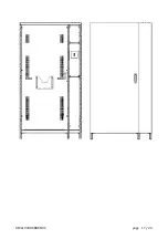
Page 17: ...0ML190480RUENUC page 17 24 ...
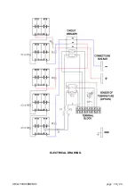
Page 18: ...0ML190480RUENUC page 18 24 ELECTRICAL DRAWING ...
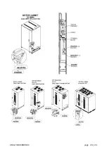
Page 20: ...0ML190480RUENUC page 20 24 ...
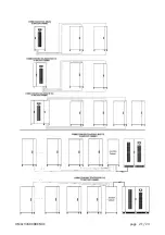
Page 21: ...0ML190480RUENUC page 21 24 ...
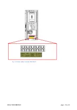
Page 23: ...0ML190480RUENUC page 23 24 Fig 14 battery cabinet terminal block detail ...
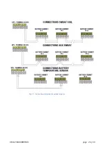
Page 24: ...0ML190480RUENUC page 24 24 Fig 15 Connections diagram of auxiliary signals ...


