0ML190480RUENUC
page 11 / 24
SECTION
4
INSTALLATION AND ASSEMBLY OF BATTERY BLOCKS
The following operations must be performed by properly trained and qualified personnel,
within a suitable area with no access to other people
WARNING!
When all the cells are connected, the voltage to the terminals could exceed 500Vdc and it is dangerous.
Risk of electric shock or burns due to accidental short circuits
Appropriate eye protection must be worn to prevent injuries from accidental electrical arcs
Risk of electrolyte leakage from batteries.
Appropriate protective clothing and accident prevention shoes must be worn to handling batteries
Remove all metal wearable objects (rings, watches, bracelets, necklaces…)
Appropriate eye protections must be worn
Tools with insulated handles only must be used
If electrolyte, leaking from batteries, comes into contact with the skin, wash immediately the part with
abundant clean water
Type of batteries to be used
Cabinet size /
model
Manufacturer
P/N
n. of
units
Cells per unit /
unit rated voltage
100 Ah / BBX 1900
480V UL L8 3U
CSB BATTERY
HRL 12390W-FR
40
6 / 12
FIAMM
12 FLX400
12FLB400
6 / 12
55 Ah / BBX 1900
480V L6 3U
CSB BATTERY
HRL 12200W-FR
40
6 / 12
FIAMM
12 FLX200
12FLB200
6 / 12
BATTERY ASSEMBLY MODE
Following the steps below, mount 8 batteries for each of the 5 trays. 40 batteries in total
Battery
dimensions max
55Ah
100Ah
L mm [in]
229 [9,01] 344.5 [13.56]
H mm [in]
212 [8.35] 220 [8.66]
W mm [in]
138 [5,43] 174 [6.85]
Weight kg [lb]
18 [39,7] 35.5 [7.2 ]
Summary of Contents for MASTER HP
Page 1: ...UNINTERRUPTIBLE POWER SUPPLY MASTER HP UL 55 100Ah BATTERY CABINET User Manual ...
Page 2: ...0ML190480RUENUC page 2 24 RPS SpA Viale Europa 7 37045 Legnago VR Italy www riello ups com ...
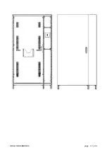
Page 17: ...0ML190480RUENUC page 17 24 ...
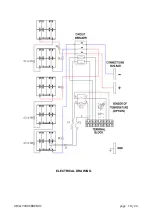
Page 18: ...0ML190480RUENUC page 18 24 ELECTRICAL DRAWING ...
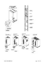
Page 20: ...0ML190480RUENUC page 20 24 ...
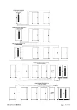
Page 21: ...0ML190480RUENUC page 21 24 ...
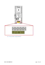
Page 23: ...0ML190480RUENUC page 23 24 Fig 14 battery cabinet terminal block detail ...
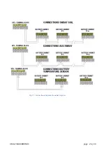
Page 24: ...0ML190480RUENUC page 24 24 Fig 15 Connections diagram of auxiliary signals ...


